Facebook Instagram Youtube Twitter

What is Velocity Boundary Layer – Thermal Boundary Layer – Definition

Similarly as a velocity boundary layer develops when there is fluid flow over a surface, a thermal boundary layer must develop if the bulk temperature and surface temperature differ. Thermal Engineering

Velocity Boundary Layer

In general, when a fluid flows over a stationary surface, e.g. the flat plate, the bed of a river, or the wall of a pipe, the fluid touching the surface is brought to rest by the shear stress to at the wall. The region in which flow adjusts from zero velocity at the wall to a maximum in the main stream of the flow is termed the boundary layer. The concept of boundary layers is of importance in all of viscous fluid dynamics and also in the theory of heat transfer.

Basic characteristics of all laminar and turbulent boundary layers are shown in the developing flow over a flat plate. The stages of the formation of the boundary layer are shown in the figure below:
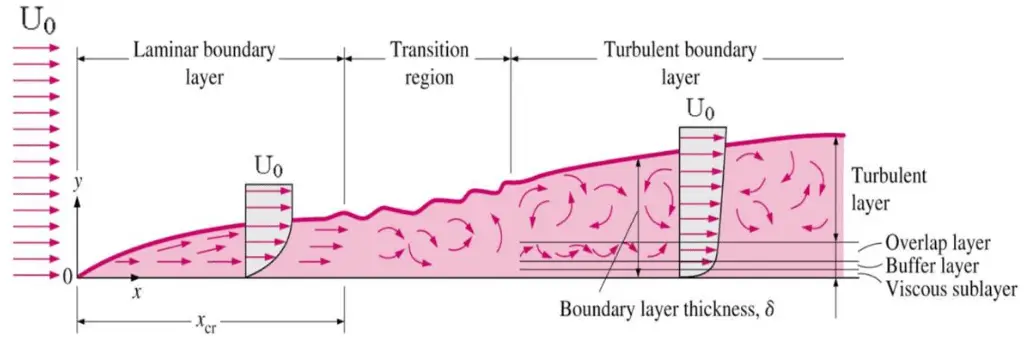
Boundary layer on flat plate

Boundary layers may be either laminar, or turbulent depending on the value of the Reynolds number.

See also: Boundary Layer

Thermal Boundary Layer
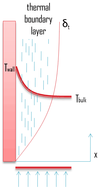
thermal boundary layer - convectionSimilarly as a velocity boundary layer develops when there is fluid flow over a surface, a thermal boundary layer must develop if the bulk temperature and surface temperature differ. Consider flow over an isothermal flat plate at a constant temperature of Twall. At the leading edge the temperature profile is uniform with Tbulk. Fluid particles that come into contact with the plate achieve thermal equilibrium at the plate’s surface temperature. At this point, energy flow occurs at the surface purely by conduction. These particles exchange energy with those in the adjoining fluid layer (by conduction and diffusion), and temperature gradients develop in the fluid. The region of the fluid in which these temperature gradients exist is the thermal boundary layer. Its thickness, δt, is typically defined as the distance from the body at which the temperature is 99% of the temperature found from an inviscid solution. With increasing distance from the leading edge, the effects of heat transfer penetrate farther into the stream and the thermal boundary layer grows.
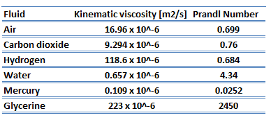
Prandtl Number - materialsThe ratio of these two thicknesses (velocity and thermal boundary layers) is governed by the Prandtl number, which is defined as the ratio of momentum diffusivity to thermal diffusivity. A Prandtl number of unity indicates that momentum and thermal diffusivity are comparable, and velocity and thermal boundary layers almost coincide with each other. If the Prandtl number is less than 1, which is the case for air at standard conditions, the thermal boundary layer is thicker than the velocity boundary layer. If the Prandtl number is greater than 1, the thermal boundary layer is thinner than the velocity boundary layer. Air at room temperature has a Prandtl number of 0.71 and for water at 18°C it is around 7.56, which means that the thermal diffusivity is more dominant for air than for water.

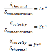
Similarly as for Prandtl Number, the Lewis number physically relates the relative thickness of the thermal layer and mass-transfer (concentration) boundary layer. The Schmidt number physically relates the relative thickness of the velocity boundary layer and mass-transfer (concentration) boundary layer.
Lewis Number - Prandtl Number - Schmidt Number

where n = 1/3  for most applications in all three relations. These relations, in general, are applicable only for laminar flow and are not applicable to turbulent boundary layers since turbulent mixing in this case may dominate the diffusion processes.

 
References:
Heat Transfer:
  1. Fundamentals of Heat and Mass Transfer, 7th Edition. Theodore L. Bergman, Adrienne S. Lavine, Frank P. Incropera. John Wiley & Sons, Incorporated, 2011. ISBN: 9781118137253.
  2. Heat and Mass Transfer. Yunus A. Cengel. McGraw-Hill Education, 2011. ISBN: 9780071077866.
  3. Fundamentals of Heat and Mass Transfer. C. P. Kothandaraman. New Age International, 2006, ISBN: 9788122417722.
  4. U.S. Department of Energy, Thermodynamics, Heat Transfer and Fluid Flow. DOE Fundamentals Handbook, Volume 2 of 3. May 2016.

Nuclear and Reactor Physics:

  1. J. R. Lamarsh, Introduction to Nuclear Reactor Theory, 2nd ed., Addison-Wesley, Reading, MA (1983).
  2. J. R. Lamarsh, A. J. Baratta, Introduction to Nuclear Engineering, 3d ed., Prentice-Hall, 2001, ISBN: 0-201-82498-1.
  3. W. M. Stacey, Nuclear Reactor Physics, John Wiley & Sons, 2001, ISBN: 0- 471-39127-1.
  4. Glasstone, Sesonske. Nuclear Reactor Engineering: Reactor Systems Engineering, Springer; 4th edition, 1994, ISBN: 978-0412985317
  5. W.S.C. Williams. Nuclear and Particle Physics. Clarendon Press; 1 edition, 1991, ISBN: 978-0198520467
  6. G.R.Keepin. Physics of Nuclear Kinetics. Addison-Wesley Pub. Co; 1st edition, 1965
  7. Robert Reed Burn, Introduction to Nuclear Reactor Operation, 1988.
  8. U.S. Department of Energy, Nuclear Physics and Reactor Theory. DOE Fundamentals Handbook, Volume 1 and 2. January 1993.
  9. Paul Reuss, Neutron Physics. EDP Sciences, 2008. ISBN: 978-2759800414.

Advanced Reactor Physics:

  1. K. O. Ott, W. A. Bezella, Introductory Nuclear Reactor Statics, American Nuclear Society, Revised edition (1989), 1989, ISBN: 0-894-48033-2.
  2. K. O. Ott, R. J. Neuhold, Introductory Nuclear Reactor Dynamics, American Nuclear Society, 1985, ISBN: 0-894-48029-4.
  3. D. L. Hetrick, Dynamics of Nuclear Reactors, American Nuclear Society, 1993, ISBN: 0-894-48453-2.
  4. E. E. Lewis, W. F. Miller, Computational Methods of Neutron Transport, American Nuclear Society, 1993, ISBN: 0-894-48452-4.

See also:

Boundary Layer

We hope, this article, Velocity Boundary Layer – Thermal Boundary Layer, helps you. If so, give us a like in the sidebar. Main purpose of this website is to help the public to learn some interesting and important information about thermal engineering.
What is Overall Heat Transfer Coefficient – U-factor – Definition

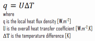
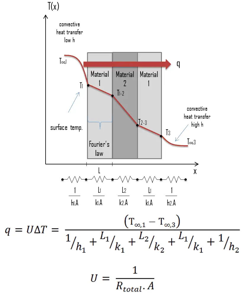
In composite systems, it is often convenient to work with an overall heat transfer coefficient, known as a U-factor. The U-factor is defined by an expression analogous to Newton’s law of cooling

U-factor – Overall Heat Transfer Coefficient

Many of the heat transfer processes encountered in industry involve composite systems and even involve a combination of both conduction and convection. With these composite systems, it is often convenient to work with an overall heat transfer coefficient, known as a U-factor. The U-factor is defined by an expression analogous to Newton’s law of cooling:

u-factor - overall heat transfer coefficient

The overall heat transfer coefficient is related to the total thermal resistance and depends on the geometry of the problem. For example, heat transfer in a steam generator involves convection from the bulk of the reactor coolant to the steam generator inner tube surface, conduction through the tube wall, and convection (boiling) from the outer tube surface to the secondary side fluid.

In cases of combined heat transfer for a heat exchanger, there are two values for h. There is the convective heat transfer coefficient (h) for the fluid film inside the tubes and a convective heat transfer coefficient for the fluid film outside the tubes. The thermal conductivity (k) and thickness (Δx) of the tube wall must also be accounted for.

Overall Heat Transfer Coefficient – Plane Wall

U-factor - Overall Heat Transfer Coefficient

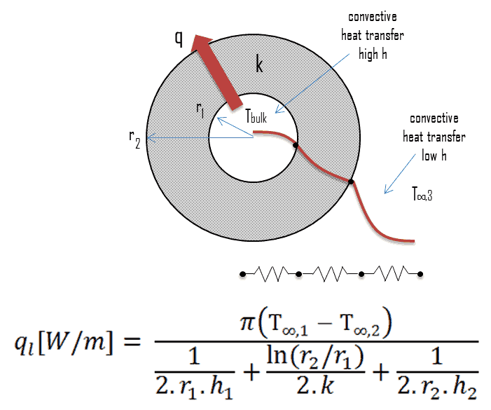
Overall Heat Transfer Coefficient – Cylindrical Tubes

Steady heat transfer through multilayered cylindrical or spherical shells can be handled just like multilayered plane walls.

Overall Heat Transfer Coefficient - Cylindrical Tubes

Thermal Conductivity

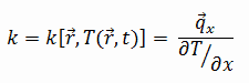
The heat transfer characteristics of a solid material are measured by a property called the thermal conductivity, k (or λ), measured in W/m.K. It is a measure of a substance’s ability to transfer heat through a material by conduction. Note that Fourier’s law applies for all matter, regardless of its state (solid, liquid, or gas), therefore, it is also defined for liquids and gases.

The thermal conductivity of most liquids and solids varies with temperature. For vapors, it also depends upon pressure. In general:

thermal conductivity - definition

Most materials are very nearly homogeneous, therefore we can usually write k = k (T). Similar definitions are associated with thermal conductivities in the y- and z-directions (ky, kz), but for an isotropic material the thermal conductivity is independent of the direction of transfer, kx = ky = kz = k.

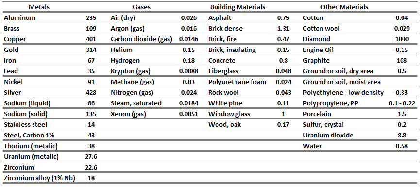
From the foregoing equation, it follows that the conduction heat flux increases with increasing thermal conductivity and increases with increasing temperature difference. In general, the thermal conductivity of a solid is larger than that of a liquid, which is larger than that of a gas. This trend is due largely to differences in intermolecular spacing for the two states of matter. In particular, diamond has the highest hardness and thermal conductivity of any bulk material.

thermal conductivity - materials

Convective Heat Transfer Coefficient

As can be seen, the constant of proportionality will be crucial in calculations and it is known as the convective heat transfer coefficient, h. The convective heat transfer coefficient, h, can be defined as:

The rate of heat transfer between a solid surface and a fluid per unit surface area per unit temperature difference.

convective heat transfer coefficient - equation

convective heat transfer coefficient - examples

The convective heat transfer coefficient is dependent upon the physical properties of the fluid and the physical situation. The convective heat transfer coefficient is not a property of the fluid. It is an experimentally determined parameter whose value depends on all the variables influencing convection such as the surface geometry, the nature of fluid motion, the properties of the fluid, and the bulk fluid velocity.

Typically, the convective heat transfer coefficient for laminar flow is relatively low compared to the convective heat transfer coefficient for turbulent flow. This is due to turbulent flow having a thinner stagnant fluid film layer on the heat transfer surface.

It must be noted, this stagnant fluid film layer plays crucial role for the convective heat transfer coefficient. It is observed, that the fluid comes to a complete stop at the surfaceand assumes a zero velocity relative to the surface. This phenomenon is known as the no-slip condition and therefore, at the surface, energy flow occurs purely by conduction. But in the next layers both conduction and diffusion-mass movement in the molecular level or macroscopic level occurs. Due to the mass movement the rate of energy transfer is higher.

 
References:
Heat Transfer:
  1. Fundamentals of Heat and Mass Transfer, 7th Edition. Theodore L. Bergman, Adrienne S. Lavine, Frank P. Incropera. John Wiley & Sons, Incorporated, 2011. ISBN: 9781118137253.
  2. Heat and Mass Transfer. Yunus A. Cengel. McGraw-Hill Education, 2011. ISBN: 9780071077866.
  3. Fundamentals of Heat and Mass Transfer. C. P. Kothandaraman. New Age International, 2006, ISBN: 9788122417722.
  4. U.S. Department of Energy, Thermodynamics, Heat Transfer and Fluid Flow. DOE Fundamentals Handbook, Volume 2 of 3. May 2016.

Nuclear and Reactor Physics:

  1. J. R. Lamarsh, Introduction to Nuclear Reactor Theory, 2nd ed., Addison-Wesley, Reading, MA (1983).
  2. J. R. Lamarsh, A. J. Baratta, Introduction to Nuclear Engineering, 3d ed., Prentice-Hall, 2001, ISBN: 0-201-82498-1.
  3. W. M. Stacey, Nuclear Reactor Physics, John Wiley & Sons, 2001, ISBN: 0- 471-39127-1.
  4. Glasstone, Sesonske. Nuclear Reactor Engineering: Reactor Systems Engineering, Springer; 4th edition, 1994, ISBN: 978-0412985317
  5. W.S.C. Williams. Nuclear and Particle Physics. Clarendon Press; 1 edition, 1991, ISBN: 978-0198520467
  6. G.R.Keepin. Physics of Nuclear Kinetics. Addison-Wesley Pub. Co; 1st edition, 1965
  7. Robert Reed Burn, Introduction to Nuclear Reactor Operation, 1988.
  8. U.S. Department of Energy, Nuclear Physics and Reactor Theory. DOE Fundamentals Handbook, Volume 1 and 2. January 1993.
  9. Paul Reuss, Neutron Physics. EDP Sciences, 2008. ISBN: 978-2759800414.

Advanced Reactor Physics:

  1. K. O. Ott, W. A. Bezella, Introductory Nuclear Reactor Statics, American Nuclear Society, Revised edition (1989), 1989, ISBN: 0-894-48033-2.
  2. K. O. Ott, R. J. Neuhold, Introductory Nuclear Reactor Dynamics, American Nuclear Society, 1985, ISBN: 0-894-48029-4.
  3. D. L. Hetrick, Dynamics of Nuclear Reactors, American Nuclear Society, 1993, ISBN: 0-894-48453-2.
  4. E. E. Lewis, W. F. Miller, Computational Methods of Neutron Transport, American Nuclear Society, 1993, ISBN: 0-894-48452-4.

See also:

Convection

We hope, this article, Overall Heat Transfer Coefficient – U-factor, helps you. If so, give us a like in the sidebar. Main purpose of this website is to help the public to learn some interesting and important information about thermal engineering.
What is Nusselt Number – Definition

The Nusselt number is a dimensionless number, named after a German engineer Wilhelm Nusselt. the Nusselt number represents the enhancement of heat transfer through a fluid layer as a result of convection. Thermal Engineering

Nusselt Number

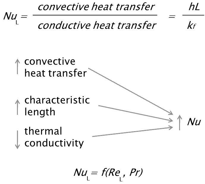
The Nusselt number is a dimensionless number, named after a German engineer Wilhelm Nusselt. The Nusselt number is closely related to Péclet number and both numbers are used to describe the ratio of the thermal energy convected to the fluid to the thermal energy conducted within the fluid. Nusselt number is equal to the dimensionless temperature gradient at the surface, and it provides a measure of the convection heat transfer occurring at the surface. The conductive component is measured under the same conditions as the heat convection but with a stagnant fluid. The Nusselt number is to the thermal boundary layer what the friction coefficient is to the velocity boundary layer. Thus, the Nusselt number is defined as:

Nusselt Number - definition

where:

kf is thermal conductivity of the fluid [W/m.K]

L is the characteristic length

h is the convective heat transfer coefficient [W/m2.K]

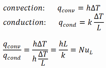
For illustration, consider a fluid layer of thickness L and temperature difference ΔT. Heat transfer through the fluid layer will be by convection when the fluid involves some motion and by conduction when the fluid layer is motionless.

In case of conduction, the heat flux can be calculated using Fourier’s law of conduction. In case of convection, the heat flux can be calculated using Newton’s law of cooling. Taking their ratio gives:

nusselt number - convection to conduction

The preceding equation defines the Nusselt number. Therefore, the Nusselt number represents the enhancement of heat transfer through a fluid layer as a result of convection relative to conduction across the same fluid layer.  A Nusselt number of Nu=1 for a fluid layer represents heat transfer across the layer by pure conduction. The larger the Nusselt number, the more effective the convection. A larger Nusselt number corresponds to more effective convection, with turbulent flow typically in the 100–1000 range. For turbulent flow, the Nusselt number is usually a function of the Reynolds number and the Prandtl number.

Correlations – Single-phase Fluid Flow

 
External Laminar Flow
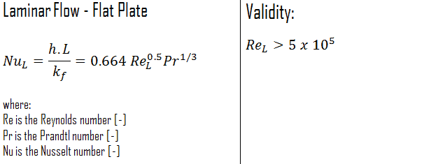
The average Nusselt number over the entire plate is determined by:

laminar flow - flat plate - nusselt number

This relation gives the average heat transfer coefficient for the entire plate when the flow is laminar over the entire plate.

Internal Laminar Flow
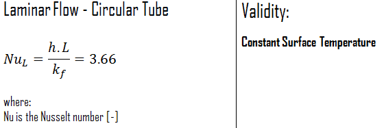
Constant Surface Temperature

In laminar flow in a tube with constant surface temperature, both the friction factor and the heat transfer coefficient remain constant in the fully developed region.

Laminar Flow - Circular Tube - temperature

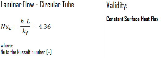
Constant Surface Heat Flux

Therefore, for fully developed laminar flow in a circular tube subjected to constant surface heat flux, the Nusselt number is a constant. There is no dependence on the Reynolds or the Prandtl numbers.

Laminar Flow - Circular Tube - flux

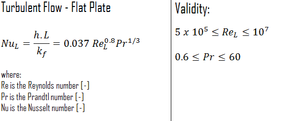
External Turbulent Flow
The average Nusselt number over the entire plate is determined by:

turbulent flow - flat plate - nusselt number

This relation gives the average heat transfer coefficient for the entire plate only when the flow is turbulent over the entire plate, or when the laminar flow region of the plate is too small relative to the turbulent flow region.

Internal Turbulent Flow - Dittus-Boelter
See also: Dittus-Boelter Equation

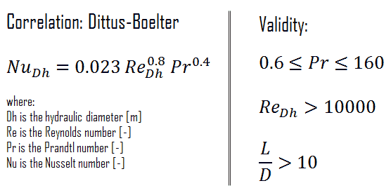
For fully developed (hydrodynamically and thermally) turbulent flow in a smooth circular tube, the local Nusselt number may be obtained from the well-known Dittus-Boelter equation. The Dittus–Boelter equation is easy to solve but is less accurate when there is a large temperature difference across the fluid and is less accurate for rough tubes (many commercial applications), since it is tailored to smooth tubes.

Dittus-Boelter Equation - Formula

The Dittus-Boelter correlation may be used for small to moderate temperature differences, Twall – Tavg, with all properties evaluated at an averaged temperature Tavg.

For flows characterized by large property variations, the corrections (e.g. a viscosity correction factor μ/μwall) must be taken into account, for example, as Sieder and Tate recommend.

Nusselt Number for Liquid Metal Reactors

See also: Nusselt Number for Liquid Metal Reactors

For liquid metals the Prandtl number is very small, generally in the range from 0.01 to 0.001. This means that the thermal diffusivity, which is related to the rate of heat transfer by conduction, unambiguously dominates. This very high thermal diffusivity results from very high thermal conductivity of metals, which is about 100 times higher than that of water. The Prandtl number for sodium at a typical operating temperature in the Sodium-cooled fast reactors is about 0.004. For this case the thermal boundary layer development is much more rapid than that of the velocity boundary layer (δt >> δ), and it is reasonable to assume uniform velocity throughout the thermal boundary layer.

Heat transfer coefficients for sodium flow through fuel channel are based on the Prandtl number and Péclet number. Pitch-to-diameter (P/D) also enters many calculations of heat transfer in liquid metal reactors. Convective heat transfer correlations are usually presented in terms of Nusselt number versus Péclet number. Typical Péclet number for normal operation are from 150 to 300 in the fuel bundles. As for another flow regimes,  the Nusselt number and a given correlation can be used to determine the convective heat transfer coefficient.

 
Graber-Rieger Correlation
Nusselt number - Liquid Metal - Graber-Rieger
FFTF Correlation
Nusselt number - Liquid Metal - FFTF

Example – Nusselt Number – Cladding Surface Temperature

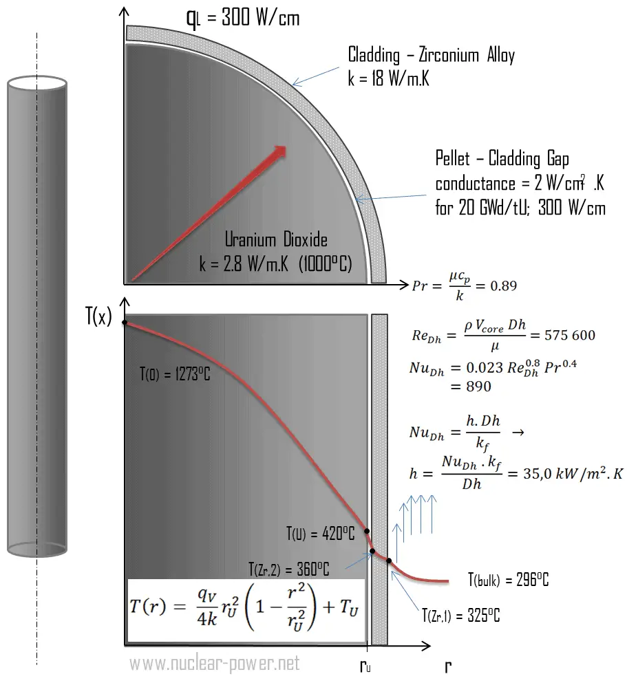
Convection - Convective Heat TransferCladding is the outer layer of the fuel rods, standing between the reactor coolant and the nuclear fuel (i.e. fuel pellets). It is made of a corrosion-resistant material with low absorption cross section for thermal neutrons, usually zirconium alloy. Cladding prevents radioactive fission products from escaping the fuel matrix into the reactor coolant and contaminating it. Cladding constitute one of barriers in ‘defence-in-depth‘ approach, therefore its coolability is one of key safety aspects.

Consider the fuel cladding of inner radius rZr,2 = 0.408 cm and outer radius rZr,1 = 0.465 cm. In comparison to fuel pellet, there is almost no heat generation in the fuel cladding (cladding is slightly heated by radiation). All heat generated in the fuel must be transferred via conduction through the cladding and therefore the inner surface is hotter than the outer surface.

Assume that:

  • the outer diameter of the cladding is: d = 2 x rZr,1 = 9,3 mm
  • the pitch of fuel pins is: p = 13 mm
  • the thermal conductivity of saturated water at 300°C is: kH2O = 0.545 W/m.K
  • the dynamic viscosity of saturated water at 300°C is: μ = 0.0000859 N.s/m2
  • the fluid density is: ρ = 714 kg/m3
  • the specific heat is: cp = 5.65 kJ/kg.K
  • the core flow velocity is constant and equal to Vcore = 5 m/s
  • the temperature of reactor coolant at this axial coordinate is: Tbulk = 296°C
  • the linear heat rate of the fuel is qL = 300 W/cm (FQ ≈ 2.0) and thus the volumetric heat rate is qV = 597 x 106 W/m3

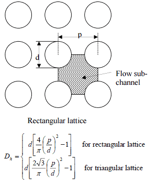
Hydraulic Diameter - Fuel ChannelCalculate the Prandtl, Reynolds and Nusselt number for this flow regime (internal forced turbulent flow) inside the rectangular fuel lattice (fuel channel), then calculate the heat transfer coefficient and finally the cladding surface temperature, TZr,1.

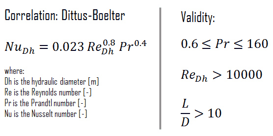
To calculate the cladding surface temperature, we have to calculate the Prandtl, Reynolds and Nusselt number, because the heat transfer for this flow regime can be described by the Dittus-Boelter equation, which is:

Dittus-Boelter Equation - Formula

Calculation of the Prandtl number

To calculate the Prandtl number, we have to know:

  • the thermal conductivity of saturated water at 300°C is: kH2O = 0.545 W/m.K
  • the dynamic viscosity of saturated water at 300°C is: μ = 0.0000859 N.s/m2
  • the specific heat is: cp = 5.65 kJ/kg.K

Note that, all these parameters significantly differs for water at 300°C from those at 20°C.  Prandtl number for water at 20°C is around 6.91. Prandtl number for reactor coolant at 300°C is then:

prandtl number - example

Calculation of the Reynolds number

To calculate the Reynolds number, we have to know:

  • the outer diameter of the cladding is: d = 2 x rZr,1 = 9,3 mm (to calculate the hydraulic diameter)
  • the pitch of fuel pins is: p = 13 mm  (to calculate the hydraulic diameter)
  • the dynamic viscosity of saturated water at 300°C is: μ = 0.0000859 N.s/m2
  • the fluid density is: ρ = 714 kg/m3

The hydraulic diameter, Dh, is a commonly used term when handling flow in non-circular tubes and channels. The hydraulic diameter of the fuel channel, Dh, is equal to 13,85 mm.

See also: Hydraulic Diameter

The Reynolds number inside the fuel channel is then equal to:

reynolds number - example

This fully satisfies the turbulent conditions.

Calculation of the Nusselt number using Dittus-Boelter equation

For fully developed (hydrodynamically and thermally) turbulent flow in a smooth circular tube, the local Nusselt number may be obtained from the well-known Dittus–Boelter equation.

To calculate the Nusselt number, we have to know:

The Nusselt number for the forced convection inside the fuel channel is then equal to:

nusselt number - example

Calculation of the heat transfer coefficient and the cladding surface temperature, TZr,1

Detailed knowledge of geometry, fluid parameters, outer radius of cladding, linear heat rate, convective heat transfer coefficient allows us to calculate the temperature difference ∆T between the coolant (Tbulk) and the cladding surface (TZr,1).

To calculate the the cladding surface temperature, we have to know:

  • the outer diameter of the cladding is: d = 2 x rZr,1 = 9,3 mm
  • the Nusselt number, which is NuDh = 890
  • the hydraulic diameter of the fuel channel is: Dh = 13,85 mm
  • the thermal conductivity of reactor coolant (300°C) is: kH2O = 0.545 W/m.K
  • the bulk temperature of reactor coolant at this axial coordinate is: Tbulk = 296°C
  • the linear heat rate of the fuel is: qL = 300 W/cm (FQ ≈ 2.0)

The convective heat transfer coefficient, h, is given directly by the definition of Nusselt number:

convective heat transfer coefficient - example

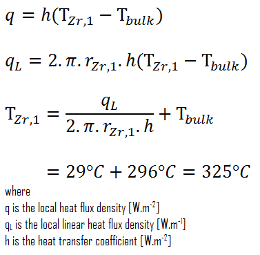
Finally, we can calculate the cladding surface temperature (TZr,1) simply using the Newton’s Law of Cooling:

Newton law of cooling - example

For PWRs at normal operation, there is a compressed liquid water inside the reactor core, loops and steam generators.  The pressure is maintained at approximately 16MPa. At this pressure water boils at approximately 350°C(662°F). As can be seen, the surface temperature TZr,1 = 325°C ensures, that even subcooled boiling does not occur. Note that, subcooled boiling requires TZr,1 = Tsat. Since the inlet temperatures of the water are usually about 290°C (554°F), it is obvious this example corresponds to the lower part of the core. At higher elevations of the core the bulk temperature may reach up to 330°C. The temperature difference of 29°C causes the subcooled boiling may occur (330°C + 29°C > 350°C). On the other hand, nucleate boiling at the surface effectively disrupts the stagnant layer and therefore nucleate boiling significantly increases the ability of a surface to transfer thermal energy to bulk fluid. As a result, the convective heat transfer coefficient significantly increases and therefore at higher elevations, the temperature difference (TZr,1 – Tbulk) significantly decreases.

 
References:
Heat Transfer:
  1. Fundamentals of Heat and Mass Transfer, 7th Edition. Theodore L. Bergman, Adrienne S. Lavine, Frank P. Incropera. John Wiley & Sons, Incorporated, 2011. ISBN: 9781118137253.
  2. Heat and Mass Transfer. Yunus A. Cengel. McGraw-Hill Education, 2011. ISBN: 9780071077866.
  3. Fundamentals of Heat and Mass Transfer. C. P. Kothandaraman. New Age International, 2006, ISBN: 9788122417722.
  4. U.S. Department of Energy, Thermodynamics, Heat Transfer and Fluid Flow. DOE Fundamentals Handbook, Volume 2 of 3. May 2016.

Nuclear and Reactor Physics:

  1. J. R. Lamarsh, Introduction to Nuclear Reactor Theory, 2nd ed., Addison-Wesley, Reading, MA (1983).
  2. J. R. Lamarsh, A. J. Baratta, Introduction to Nuclear Engineering, 3d ed., Prentice-Hall, 2001, ISBN: 0-201-82498-1.
  3. W. M. Stacey, Nuclear Reactor Physics, John Wiley & Sons, 2001, ISBN: 0- 471-39127-1.
  4. Glasstone, Sesonske. Nuclear Reactor Engineering: Reactor Systems Engineering, Springer; 4th edition, 1994, ISBN: 978-0412985317
  5. W.S.C. Williams. Nuclear and Particle Physics. Clarendon Press; 1 edition, 1991, ISBN: 978-0198520467
  6. G.R.Keepin. Physics of Nuclear Kinetics. Addison-Wesley Pub. Co; 1st edition, 1965
  7. Robert Reed Burn, Introduction to Nuclear Reactor Operation, 1988.
  8. U.S. Department of Energy, Nuclear Physics and Reactor Theory. DOE Fundamentals Handbook, Volume 1 and 2. January 1993.
  9. Paul Reuss, Neutron Physics. EDP Sciences, 2008. ISBN: 978-2759800414.

Advanced Reactor Physics:

  1. K. O. Ott, W. A. Bezella, Introductory Nuclear Reactor Statics, American Nuclear Society, Revised edition (1989), 1989, ISBN: 0-894-48033-2.
  2. K. O. Ott, R. J. Neuhold, Introductory Nuclear Reactor Dynamics, American Nuclear Society, 1985, ISBN: 0-894-48029-4.
  3. D. L. Hetrick, Dynamics of Nuclear Reactors, American Nuclear Society, 1993, ISBN: 0-894-48453-2.
  4. E. E. Lewis, W. F. Miller, Computational Methods of Neutron Transport, American Nuclear Society, 1993, ISBN: 0-894-48452-4.

See also:

Characteristic Numbers

We hope, this article, Nusselt Number, helps you. If so, give us a like in the sidebar. Main purpose of this website is to help the public to learn some interesting and important information about thermal engineering.
What is Convection Example – Problem with Solution – Definition

This example shows, how to calculate convective heat transfer. Calculation of the heat transfer coefficient and the cladding surface temperature. Thermal Engineering

Example – Convection – Cladding Surface Temperature

Convection - Convective Heat Transfer

Example – Convection – Problem with Solution 

Cladding is the outer layer of the fuel rods, standing between the reactor coolant and the nuclear fuel (i.e. fuel pellets). It is made of a corrosion-resistant material with low absorption cross section for thermal neutrons, usually zirconium alloy. Cladding prevents radioactive fission products from escaping the fuel matrix into the reactor coolant and contaminating it. Cladding constitute one of barriers in ‘defence-in-depth‘ approach, therefore its coolability is one of key safety aspects.

Consider the fuel cladding of inner radius rZr,2 = 0.408 cm and outer radius rZr,1 = 0.465 cm. In comparison to fuel pellet, there is almost no heat generation in the fuel cladding (cladding is slightly heated by radiation). All heat generated in the fuel must be transferred via conduction through the cladding and therefore the inner surface is hotter than the outer surface.

Assume that:

  • the outer diameter of the cladding is: d = 2 x rZr,1 = 9,3 mm
  • the pitch of fuel pins is: p = 13 mm
  • the thermal conductivity of saturated water at 300°C is: kH2O = 0.545 W/m.K
  • the dynamic viscosity of saturated water at 300°C is: μ = 0.0000859 N.s/m2
  • the fluid density is: ρ = 714 kg/m3
  • the specific heat is: cp = 5.65 kJ/kg.K
  • the core flow velocity is constant and equal to Vcore = 5 m/s
  • the temperature of reactor coolant at this axial coordinate is: Tbulk = 296°C
  • the linear heat rate of the fuel is qL = 300 W/cm (FQ ≈ 2.0) and thus the volumetric heat rate is qV = 597 x 106 W/m3

Hydraulic Diameter - Fuel ChannelCalculate the Prandtl, Reynolds and Nusselt number for this flow regime (internal forced turbulent flow) inside the rectangular fuel lattice (fuel channel), then calculate the heat transfer coefficient and finally the cladding surface temperature, TZr,1.

To calculate the cladding surface temperature, we have to calculate the Prandtl, Reynolds and Nusselt number, because the heat transfer for this flow regime can be described by the Dittus-Boelter equation, which is:

Dittus-Boelter Equation - Formula

Calculation of the Prandtl number

To calculate the Prandtl number, we have to know:

  • the thermal conductivity of saturated water at 300°C is: kH2O = 0.545 W/m.K
  • the dynamic viscosity of saturated water at 300°C is: μ = 0.0000859 N.s/m2
  • the specific heat is: cp = 5.65 kJ/kg.K

Note that, all these parameters significantly differs for water at 300°C from those at 20°C.  Prandtl number for water at 20°C is around 6.91. Prandtl number for reactor coolant at 300°C is then:

prandtl number - example

Calculation of the Reynolds number

To calculate the Reynolds number, we have to know:

  • the outer diameter of the cladding is: d = 2 x rZr,1 = 9,3 mm (to calculate the hydraulic diameter)
  • the pitch of fuel pins is: p = 13 mm  (to calculate the hydraulic diameter)
  • the dynamic viscosity of saturated water at 300°C is: μ = 0.0000859 N.s/m2
  • the fluid density is: ρ = 714 kg/m3

The hydraulic diameter, Dh, is a commonly used term when handling flow in non-circular tubes and channels. The hydraulic diameter of the fuel channel, Dh, is equal to 13,85 mm.

See also: Hydraulic Diameter

The Reynolds number inside the fuel channel is then equal to:

reynolds number - example

This fully satisfies the turbulent conditions.

Calculation of the Nusselt number using Dittus-Boelter equation

For fully developed (hydrodynamically and thermally) turbulent flow in a smooth circular tube, the local Nusselt number may be obtained from the well-known Dittus–Boelter equation.

To calculate the Nusselt number, we have to know:

The Nusselt number for the forced convection inside the fuel channel is then equal to:

nusselt number - example

Calculation of the heat transfer coefficient and the cladding surface temperature, TZr,1

Detailed knowledge of geometry, fluid parameters, outer radius of cladding, linear heat rate, convective heat transfer coefficient allows us to calculate the temperature difference ∆T between the coolant (Tbulk) and the cladding surface (TZr,1).

To calculate the the cladding surface temperature, we have to know:

  • the outer diameter of the cladding is: d = 2 x rZr,1 = 9,3 mm
  • the Nusselt number, which is NuDh = 890
  • the hydraulic diameter of the fuel channel is: Dh = 13,85 mm
  • the thermal conductivity of reactor coolant (300°C) is: kH2O = 0.545 W/m.K
  • the bulk temperature of reactor coolant at this axial coordinate is: Tbulk = 296°C
  • the linear heat rate of the fuel is: qL = 300 W/cm (FQ ≈ 2.0)

The convective heat transfer coefficient, h, is given directly by the definition of Nusselt number:

convective heat transfer coefficient - example

Finally, we can calculate the cladding surface temperature (TZr,1) simply using the Newton’s Law of Cooling:

Newton law of cooling - example

For PWRs at normal operation, there is a compressed liquid water inside the reactor core, loops and steam generators.  The pressure is maintained at approximately 16MPa. At this pressure water boils at approximately 350°C(662°F). As can be seen, the surface temperature TZr,1 = 325°C ensures, that even subcooled boiling does not occur. Note that, subcooled boiling requires TZr,1 = Tsat. Since the inlet temperatures of the water are usually about 290°C (554°F), it is obvious this example corresponds to the lower part of the core. At higher elevations of the core the bulk temperature may reach up to 330°C. The temperature difference of 29°C causes the subcooled boiling may occur (330°C + 29°C > 350°C). On the other hand, nucleate boiling at the surface effectively disrupts the stagnant layer and therefore nucleate boiling significantly increases the ability of a surface to transfer thermal energy to bulk fluid. As a result, the convective heat transfer coefficient significantly increases and therefore at higher elevations, the temperature difference (TZr,1 – Tbulk) significantly decreases.

 
References:
Heat Transfer:
  1. Fundamentals of Heat and Mass Transfer, 7th Edition. Theodore L. Bergman, Adrienne S. Lavine, Frank P. Incropera. John Wiley & Sons, Incorporated, 2011. ISBN: 9781118137253.
  2. Heat and Mass Transfer. Yunus A. Cengel. McGraw-Hill Education, 2011. ISBN: 9780071077866.
  3. Fundamentals of Heat and Mass Transfer. C. P. Kothandaraman. New Age International, 2006, ISBN: 9788122417722.
  4. U.S. Department of Energy, Thermodynamics, Heat Transfer and Fluid Flow. DOE Fundamentals Handbook, Volume 2 of 3. May 2016.

Nuclear and Reactor Physics:

  1. J. R. Lamarsh, Introduction to Nuclear Reactor Theory, 2nd ed., Addison-Wesley, Reading, MA (1983).
  2. J. R. Lamarsh, A. J. Baratta, Introduction to Nuclear Engineering, 3d ed., Prentice-Hall, 2001, ISBN: 0-201-82498-1.
  3. W. M. Stacey, Nuclear Reactor Physics, John Wiley & Sons, 2001, ISBN: 0- 471-39127-1.
  4. Glasstone, Sesonske. Nuclear Reactor Engineering: Reactor Systems Engineering, Springer; 4th edition, 1994, ISBN: 978-0412985317
  5. W.S.C. Williams. Nuclear and Particle Physics. Clarendon Press; 1 edition, 1991, ISBN: 978-0198520467
  6. G.R.Keepin. Physics of Nuclear Kinetics. Addison-Wesley Pub. Co; 1st edition, 1965
  7. Robert Reed Burn, Introduction to Nuclear Reactor Operation, 1988.
  8. U.S. Department of Energy, Nuclear Physics and Reactor Theory. DOE Fundamentals Handbook, Volume 1 and 2. January 1993.
  9. Paul Reuss, Neutron Physics. EDP Sciences, 2008. ISBN: 978-2759800414.

Advanced Reactor Physics:

  1. K. O. Ott, W. A. Bezella, Introductory Nuclear Reactor Statics, American Nuclear Society, Revised edition (1989), 1989, ISBN: 0-894-48033-2.
  2. K. O. Ott, R. J. Neuhold, Introductory Nuclear Reactor Dynamics, American Nuclear Society, 1985, ISBN: 0-894-48029-4.
  3. D. L. Hetrick, Dynamics of Nuclear Reactors, American Nuclear Society, 1993, ISBN: 0-894-48453-2.
  4. E. E. Lewis, W. F. Miller, Computational Methods of Neutron Transport, American Nuclear Society, 1993, ISBN: 0-894-48452-4.

See also:

Convection

We hope, this article, Convection Example – Problem with Solution, helps you. If so, give us a like in the sidebar. Main purpose of this website is to help the public to learn some interesting and important information about thermal engineering.
What is Thermal Energy – Definition

Thermal Energy – Definition. Thermal energy (also called the internal energy) is defined as the energy associated with microscopic forms of energy. Thermal Engineering

Thermal Energy – Definition

Thermal Energy – Definition

In thermodynamics, thermal energy (also called the internal energy) is defined as the energy associated with microscopic forms of energy. It is an extensive quantity, it depends on the size of the system, or on the amount of substance it contains. The SI unit of thermal energy is the joule (J). It is the energy contained within the system, excluding the kinetic energy of motion of the system as a whole and the potential energy of the system. Microscopic forms of energy include those due to the rotation, vibration, translation, and interactions among the molecules of a substance. None of these forms of energy can be measured or evaluated directly, but techniques have been developed to evaluate the change in the total sum of all these microscopic forms of energy.

Microscopic Energy

Thermal Energy – Definition

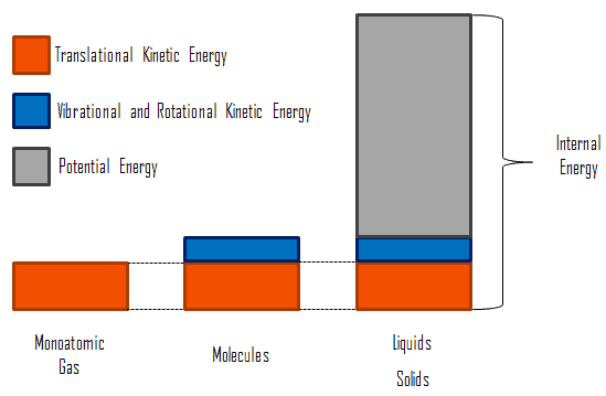
Internal energy involves energy on the microscopic scale. It may be divided into microscopic potential energy, Upot, and microscopic kinetic energy, Ukin, components:

U = Upot + Ukin

Microscopic Energy - Internal Energywhere the microscopic kinetic energy, Ukin, involves the motions of all the system’s particles with respect to the center-of-mass frame. For an ideal monatomic gas, this is just the translational kinetic energy of the linear motion of the atoms. Monoatomic particles do not rotate or vibrate. The behavior of the system is well described by kinetic theory of gases. Kinetic theory is based on the fact that during an elastic collision between a molecule with high kinetic energy and one with low kinetic energy, part of energy will transfer to the molecule of lower kinetic energy. However, for polyatomic gases there is rotational and vibrational kinetic energy as well.

The microscopic potential energy, Upot, involves the chemical bonds between the atoms that make up the molecules, binding forces in the nucleus and also the physical force fields within the system (e.g. electric or magnetic fields).

In liquids and solids there is significant component of potential energy associated with the intermolecular attractive forces.

Thermal Energy and Heat

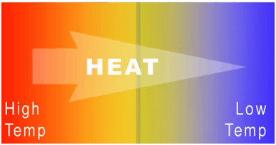
zeroth-law-of-thermodynamics-heatWhile thermal energy refers to the total energy of all the molecules within the object, heat is the amount of energy flowing from one body to another spontaneously due to their temperature difference. Heat is a form of energy, but it is energy in transit. Heat is not a property of a system. However, the transfer of energy as heat occurs at the molecular level as a result of a temperature difference.

Consider a block of metal at high temperature, that consists of atoms that are oscillating intensely around their average positions. At low temperatures, the atoms continue to oscillate, but with less intensity. If a hotter block of metal is put in contact with a cooler block, the intensely oscillating atoms at the edge of the hotter block gives off its kinetic energy to the less oscillating atoms at the edge of the cool block. In this case there is energy transfer between these two blocks and heat flows from the hotter to the cooler block by this random vibrations.

Distinguishing Temperature, Heat, and Thermal Energy

Using the kinetic theory, a clear distinction between these three properties can be made.

  • Temperature is related to the kinetic energies of the molecules of a material. It is the average kinetic energy of individual molecules.
  • Internal energy refers to the total energy of all the molecules within the object. It is an extensive property, therefore when two equal-mass hot ingots of steel may have the same temperature, but two of them have twice as much internal energy as one does.
  • Finally, heat is the amount of energy flowing from one body to another spontaneously due to their temperature difference.

It must be added, when a temperature difference does exist heat flows spontaneously from the warmer system to the colder system. Thus, if a 5 kg cube of steel at 100°C is placed in contact with a 500 kg cube of steel at 20°C, heat flows from the cube at 300°C to the cube at 20°C even though the internal energy of the 20°C cube is much greater because there is so much more of it.

A particularly important concept is thermodynamic equilibrium. In general, when two objects are brought into thermal contact, heat will flow between them until they come into equilibrium with each other.

Thermal Conductivity

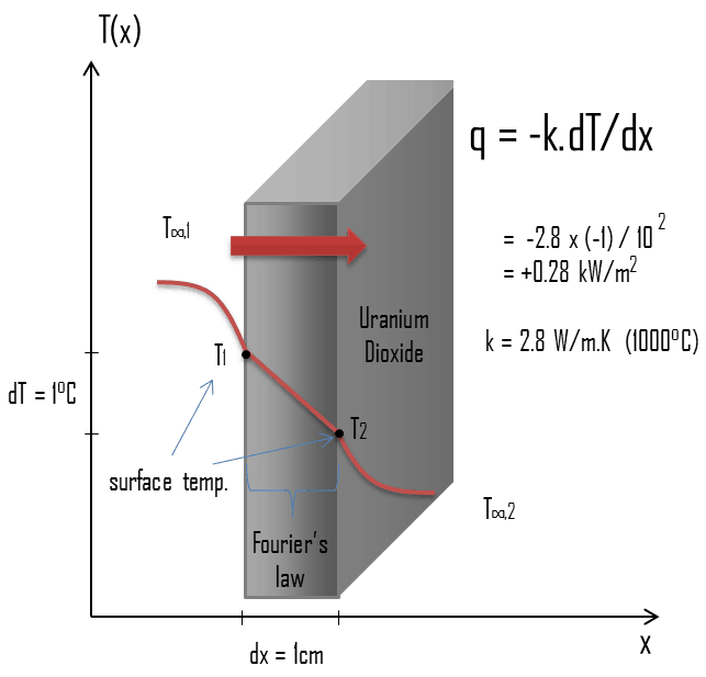
Thermal conduction - thermal conductivity - uranium dioxideThe heat transfer characteristics of a solid material are measured by a property called the thermal conductivity, k (or λ), measured in W/m.K. It is a measure of a substance’s ability to transfer heat through a material by conduction. Note that Fourier’s law applies for all matter, regardless of its state (solid, liquid, or gas), therefore, it is also defined for liquids and gases.

The thermal conductivity of most liquids and solids varies with temperature. For vapors, it also depends upon pressure. In general:

thermal conductivity - definition

Most materials are very nearly homogeneous, therefore we can usually write k = k (T). Similar definitions are associated with thermal conductivities in the y- and z-directions (ky, kz), but for an isotropic material the thermal conductivity is independent of the direction of transfer, kx = ky = kz = k.

From the foregoing equation, it follows that the conduction heat flux increases with increasing thermal conductivity and increases with increasing temperature difference. In general, the thermal conductivity of a solid is larger than that of a liquid, which is larger than that of a gas. This trend is due largely to differences in intermolecular spacing for the two states of matter. In particular, diamond has the highest hardness and thermal conductivity of any bulk material.

thermal conductivity - materials

Internal Energy and the First Law of Thermodynamics

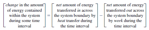
In thermodynamics the concept of energy is broadened to account for other observed changes, and the principle of conservation of energy is extended to include a wide variety of ways in which systems interact with their surroundings. The only ways the energy of a closed system can be changed are through transfer of energy by work or by heat. Further, based on the experiments of Joule and others, a fundamental aspect of the energy concept is that energy is conserved. This principle is known as the first law of thermodynamics. The first law of thermodynamics can be written in various forms:

In words:

first-law-of-thermodynamics-in-words

conservation-of-energy-in-thermodynamics
Physical layout of the four main devices used in the Rankine cycle and basic energy transfers.

Equation form:

∆Eint = Q – W

where Eint represents the internal energy of the material, which depends only on the material’s state (temperature, pressure, and volume). Q is the net heat added to the system and W is the net work done by the system. We must be careful and consistent in following the sign conventions for Q and W. Because W in the equation is the work done by the system, then if work is done on the system, W will be negative and Eint will increase.

Similarly, Q is positive for heat added to the system, so if heat leaves the system, Q is negative. This tells us the following: The internal energy of a system tends to increase if heat is absorbed by the system or if positive work is done on the system. Conversely, the internal energy tends to decrease if heat is lost by the system or if negative work is done on the system. It must be added Q and W are path dependent, while Eint is path independent.

Differential form:

dEint = dQ  – dW

The internal energy Eint of a system tends to increase if energy is added as heat Q and tends to decrease if energy is lost as work W done by the system.

See also: Open System – Closed System – Isolated System

 
References:
Nuclear and Reactor Physics:
  1. J. R. Lamarsh, Introduction to Nuclear Reactor Theory, 2nd ed., Addison-Wesley, Reading, MA (1983).
  2. J. R. Lamarsh, A. J. Baratta, Introduction to Nuclear Engineering, 3d ed., Prentice-Hall, 2001, ISBN: 0-201-82498-1.
  3. W. M. Stacey, Nuclear Reactor Physics, John Wiley & Sons, 2001, ISBN: 0- 471-39127-1.
  4. Glasstone, Sesonske. Nuclear Reactor Engineering: Reactor Systems Engineering, Springer; 4th edition, 1994, ISBN: 978-0412985317
  5. W.S.C. Williams. Nuclear and Particle Physics. Clarendon Press; 1 edition, 1991, ISBN: 978-0198520467
  6. Kenneth S. Krane. Introductory Nuclear Physics, 3rd Edition, Wiley, 1987, ISBN: 978-0471805533
  7. G.R.Keepin. Physics of Nuclear Kinetics. Addison-Wesley Pub. Co; 1st edition, 1965
  8. Robert Reed Burn, Introduction to Nuclear Reactor Operation, 1988.
  9. U.S. Department of Energy, Nuclear Physics and Reactor Theory. DOE Fundamentals Handbook, Volume 1 and 2. January 1993.

Advanced Reactor Physics:

  1. K. O. Ott, W. A. Bezella, Introductory Nuclear Reactor Statics, American Nuclear Society, Revised edition (1989), 1989, ISBN: 0-894-48033-2.
  2. K. O. Ott, R. J. Neuhold, Introductory Nuclear Reactor Dynamics, American Nuclear Society, 1985, ISBN: 0-894-48029-4.
  3. D. L. Hetrick, Dynamics of Nuclear Reactors, American Nuclear Society, 1993, ISBN: 0-894-48453-2.
  4. E. E. Lewis, W. F. Miller, Computational Methods of Neutron Transport, American Nuclear Society, 1993, ISBN: 0-894-48452-4.

See also:

Thermal Energy

We hope, this article, Thermal Energy, helps you. If so, give us a like in the sidebar. Main purpose of this website is to help the public to learn some interesting and important information about thermal engineering.

What is Thermal Energy and Heat – Definition

While thermal energy refers to the total energy of all the molecules within the object, heat is the amount of energy flowing from one body to another spontaneously due to their temperature difference. Thermal Engineering

Thermal Energy and Heat

zeroth-law-of-thermodynamics-heat


Thermal Energy and Heat

While thermal energy refers to the total energy of all the molecules within the object, heat is the amount of energy flowing from one body to another spontaneously due to their temperature difference. Heat is a form of energy, but it is energy in transit. Heat is not a property of a system. However, the transfer of energy as heat occurs at the molecular level as a result of a temperature difference.

Consider a block of metal at high temperature, that consists of atoms that are oscillating intensely around their average positions. At low temperatures, the atoms continue to oscillate, but with less intensity. If a hotter block of metal is put in contact with a cooler block, the intensely oscillating atoms at the edge of the hotter block gives off its kinetic energy to the less oscillating atoms at the edge of the cool block. In this case there is energy transfer between these two blocks and heat flows from the hotter to the cooler block by this random vibrations.

Distinguishing Temperature, Heat, and Thermal Energy

Using the kinetic theory, a clear distinction between these three properties can be made.

  • Temperature is related to the kinetic energies of the molecules of a material. It is the average kinetic energy of individual molecules.
  • Internal energy refers to the total energy of all the molecules within the object. It is an extensive property, therefore when two equal-mass hot ingots of steel may have the same temperature, but two of them have twice as much internal energy as one does.
  • Finally, heat is the amount of energy flowing from one body to another spontaneously due to their temperature difference.

It must be added, when a temperature difference does exist heat flows spontaneously from the warmer system to the colder system. Thus, if a 5 kg cube of steel at 100°C is placed in contact with a 500 kg cube of steel at 20°C, heat flows from the cube at 300°C to the cube at 20°C even though the internal energy of the 20°C cube is much greater because there is so much more of it.

A particularly important concept is thermodynamic equilibrium. In general, when two objects are brought into thermal contact, heat will flow between them until they come into equilibrium with each other.

Microscopic Energy

Thermal Energy – Definition

Internal energy involves energy on the microscopic scale. It may be divided into microscopic potential energy, Upot, and microscopic kinetic energy, Ukin, components:

U = Upot + Ukin

Microscopic Energy - Internal Energywhere the microscopic kinetic energy, Ukin, involves the motions of all the system’s particles with respect to the center-of-mass frame. For an ideal monatomic gas, this is just the translational kinetic energy of the linear motion of the atoms. Monoatomic particles do not rotate or vibrate. The behavior of the system is well described by kinetic theory of gases. Kinetic theory is based on the fact that during an elastic collision between a molecule with high kinetic energy and one with low kinetic energy, part of energy will transfer to the molecule of lower kinetic energy. However, for polyatomic gases there is rotational and vibrational kinetic energy as well.

The microscopic potential energy, Upot, involves the chemical bonds between the atoms that make up the molecules, binding forces in the nucleus and also the physical force fields within the system (e.g. electric or magnetic fields).

In liquids and solids there is significant component of potential energy associated with the intermolecular attractive forces.

Thermal Conductivity

Thermal conduction - thermal conductivity - uranium dioxideThe heat transfer characteristics of a solid material are measured by a property called the thermal conductivity, k (or λ), measured in W/m.K. It is a measure of a substance’s ability to transfer heat through a material by conduction. Note that Fourier’s law applies for all matter, regardless of its state (solid, liquid, or gas), therefore, it is also defined for liquids and gases.

The thermal conductivity of most liquids and solids varies with temperature. For vapors, it also depends upon pressure. In general:

thermal conductivity - definition

Most materials are very nearly homogeneous, therefore we can usually write k = k (T). Similar definitions are associated with thermal conductivities in the y- and z-directions (ky, kz), but for an isotropic material the thermal conductivity is independent of the direction of transfer, kx = ky = kz = k.

From the foregoing equation, it follows that the conduction heat flux increases with increasing thermal conductivity and increases with increasing temperature difference. In general, the thermal conductivity of a solid is larger than that of a liquid, which is larger than that of a gas. This trend is due largely to differences in intermolecular spacing for the two states of matter. In particular, diamond has the highest hardness and thermal conductivity of any bulk material.

thermal conductivity - materials

 
References:
Nuclear and Reactor Physics:
  1. J. R. Lamarsh, Introduction to Nuclear Reactor Theory, 2nd ed., Addison-Wesley, Reading, MA (1983).
  2. J. R. Lamarsh, A. J. Baratta, Introduction to Nuclear Engineering, 3d ed., Prentice-Hall, 2001, ISBN: 0-201-82498-1.
  3. W. M. Stacey, Nuclear Reactor Physics, John Wiley & Sons, 2001, ISBN: 0- 471-39127-1.
  4. Glasstone, Sesonske. Nuclear Reactor Engineering: Reactor Systems Engineering, Springer; 4th edition, 1994, ISBN: 978-0412985317
  5. W.S.C. Williams. Nuclear and Particle Physics. Clarendon Press; 1 edition, 1991, ISBN: 978-0198520467
  6. Kenneth S. Krane. Introductory Nuclear Physics, 3rd Edition, Wiley, 1987, ISBN: 978-0471805533
  7. G.R.Keepin. Physics of Nuclear Kinetics. Addison-Wesley Pub. Co; 1st edition, 1965
  8. Robert Reed Burn, Introduction to Nuclear Reactor Operation, 1988.
  9. U.S. Department of Energy, Nuclear Physics and Reactor Theory. DOE Fundamentals Handbook, Volume 1 and 2. January 1993.

Advanced Reactor Physics:

  1. K. O. Ott, W. A. Bezella, Introductory Nuclear Reactor Statics, American Nuclear Society, Revised edition (1989), 1989, ISBN: 0-894-48033-2.
  2. K. O. Ott, R. J. Neuhold, Introductory Nuclear Reactor Dynamics, American Nuclear Society, 1985, ISBN: 0-894-48029-4.
  3. D. L. Hetrick, Dynamics of Nuclear Reactors, American Nuclear Society, 1993, ISBN: 0-894-48453-2.
  4. E. E. Lewis, W. F. Miller, Computational Methods of Neutron Transport, American Nuclear Society, 1993, ISBN: 0-894-48452-4.

See also:

Thermal Energy

We hope, this article, Thermal Energy and Heat, helps you. If so, give us a like in the sidebar. Main purpose of this website is to help the public to learn some interesting and important information about thermal engineering.

What is Dittus-Boelter Equation – Definition

The local Nusselt number may be obtained from the well-known Dittus-Boelter equation. The Dittus–Boelter equation is easy to solve but is less accurate when there is a large temperature difference

Dittus-Boelter Equation

For fully developed (hydrodynamically and thermally) turbulent flow in a smooth circular tube, the local Nusselt number may be obtained from the well-known Dittus-Boelter equation. The Dittus–Boelter equation is easy to solve but is less accurate when there is a large temperature difference across the fluid and is less accurate for rough tubes (many commercial applications), since it is tailored to smooth tubes.

Dittus-Boelter Equation - Formula

The Dittus-Boelter correlation may be used for small to moderate temperature differences, Twall – Tavg, with all properties evaluated at an averaged temperature Tavg.

For flows characterized by large property variations, the corrections (e.g. a viscosity correction factor μ/μwall) must be taken into account, for example, as Sieder and Tate recommend.

Sieder-Tate Equation

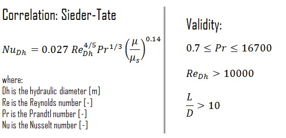
When the difference between the surface and the fluid temperatures is large, it may be necessary to account for the variation of viscosity with temperature. Therefore a modified form of Dittus-Boelter equation was proposed by Sieder and Tate (1936).

Sieder-Tate Equation - correlation

ss

Gnielinski Equation

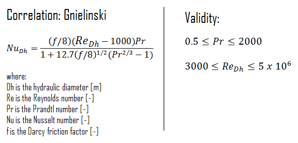
Although the Dittus-Boelter and Sieder-Tate equations are easily applied and are certainly satisfactory for the purposes of this article, errors as large as 25% may result from their use. Such errors may be reduced through the use of more recent, but generally more complex, correlations such as the Gnielinski correlation. This equation is valid for tubes over a large Reynolds number range including the transition region.

Gnielinski equation - correlation

The Darcy friction factor, f, is a dimensionless quantity used in the Darcy–Weisbach equation, for the description of frictional losses in pipe or duct as well as for open-channel flow. This is also called the Darcy–Weisbach friction factor, resistance coefficient, or simply friction factor.

Rough-walled Tubes

We also note that all these equations pertain to smooth tubes. For turbulent flow in rough tubes, the heat transfer coefficient increases with wall roughness. As the Reynolds number increases, the viscous sublayer becommes thinner and smaller. At very high Reynolds number the viscous sublayer becomes so thin that the surface roughness protrudes into the flow. The frictional losses in this case are produced in the main flow primarily by the protruding roughness elements, and the contribution of the laminar sublayer is negligible.

Special Reference: A Heat Transfer Textbook,  John H. Lienhard IV and John H. Lienhard V. Phlogiston Press, 2012.

Example – Dittus-Boelter Equation – Cladding Surface Temperature

Convection - Convective Heat TransferCladding is the outer layer of the fuel rods, standing between the reactor coolant and the nuclear fuel (i.e. fuel pellets). It is made of a corrosion-resistant material with low absorption cross section for thermal neutrons, usually zirconium alloy. Cladding prevents radioactive fission products from escaping the fuel matrix into the reactor coolant and contaminating it. Cladding constitute one of barriers in ‘defence-in-depth‘ approach, therefore its coolability is one of key safety aspects.

Consider the fuel cladding of inner radius rZr,2 = 0.408 cm and outer radius rZr,1 = 0.465 cm. In comparison to fuel pellet, there is almost no heat generation in the fuel cladding (cladding is slightly heated by radiation). All heat generated in the fuel must be transferred via conduction through the cladding and therefore the inner surface is hotter than the outer surface.

Assume that:

  • the outer diameter of the cladding is: d = 2 x rZr,1 = 9,3 mm
  • the pitch of fuel pins is: p = 13 mm
  • the thermal conductivity of saturated water at 300°C is: kH2O = 0.545 W/m.K
  • the dynamic viscosity of saturated water at 300°C is: μ = 0.0000859 N.s/m2
  • the fluid density is: ρ = 714 kg/m3
  • the specific heat is: cp = 5.65 kJ/kg.K
  • the core flow velocity is constant and equal to Vcore = 5 m/s
  • the temperature of reactor coolant at this axial coordinate is: Tbulk = 296°C
  • the linear heat rate of the fuel is qL = 300 W/cm (FQ ≈ 2.0) and thus the volumetric heat rate is qV = 597 x 106 W/m3

Hydraulic Diameter - Fuel ChannelCalculate the Prandtl, Reynolds and Nusselt number for this flow regime (internal forced turbulent flow) inside the rectangular fuel lattice (fuel channel), then calculate the heat transfer coefficient and finally the cladding surface temperature, TZr,1.

To calculate the cladding surface temperature, we have to calculate the Prandtl, Reynolds and Nusselt number, because the heat transfer for this flow regime can be described by the Dittus-Boelter equation, which is:

Dittus-Boelter Equation - Formula

Calculation of the Prandtl number

To calculate the Prandtl number, we have to know:

  • the thermal conductivity of saturated water at 300°C is: kH2O = 0.545 W/m.K
  • the dynamic viscosity of saturated water at 300°C is: μ = 0.0000859 N.s/m2
  • the specific heat is: cp = 5.65 kJ/kg.K

Note that, all these parameters significantly differs for water at 300°C from those at 20°C.  Prandtl number for water at 20°C is around 6.91. Prandtl number for reactor coolant at 300°C is then:

prandtl number - example

Calculation of the Reynolds number

To calculate the Reynolds number, we have to know:

  • the outer diameter of the cladding is: d = 2 x rZr,1 = 9,3 mm (to calculate the hydraulic diameter)
  • the pitch of fuel pins is: p = 13 mm  (to calculate the hydraulic diameter)
  • the dynamic viscosity of saturated water at 300°C is: μ = 0.0000859 N.s/m2
  • the fluid density is: ρ = 714 kg/m3

The hydraulic diameter, Dh, is a commonly used term when handling flow in non-circular tubes and channels. The hydraulic diameter of the fuel channel, Dh, is equal to 13,85 mm.

See also: Hydraulic Diameter

The Reynolds number inside the fuel channel is then equal to:

reynolds number - example

This fully satisfies the turbulent conditions.

Calculation of the Nusselt number using Dittus-Boelter equation

For fully developed (hydrodynamically and thermally) turbulent flow in a smooth circular tube, the local Nusselt number may be obtained from the well-known Dittus–Boelter equation.

To calculate the Nusselt number, we have to know:

The Nusselt number for the forced convection inside the fuel channel is then equal to:

nusselt number - example

Calculation of the heat transfer coefficient and the cladding surface temperature, TZr,1

Detailed knowledge of geometry, fluid parameters, outer radius of cladding, linear heat rate, convective heat transfer coefficient allows us to calculate the temperature difference ∆T between the coolant (Tbulk) and the cladding surface (TZr,1).

To calculate the the cladding surface temperature, we have to know:

  • the outer diameter of the cladding is: d = 2 x rZr,1 = 9,3 mm
  • the Nusselt number, which is NuDh = 890
  • the hydraulic diameter of the fuel channel is: Dh = 13,85 mm
  • the thermal conductivity of reactor coolant (300°C) is: kH2O = 0.545 W/m.K
  • the bulk temperature of reactor coolant at this axial coordinate is: Tbulk = 296°C
  • the linear heat rate of the fuel is: qL = 300 W/cm (FQ ≈ 2.0)

The convective heat transfer coefficient, h, is given directly by the definition of Nusselt number:

convective heat transfer coefficient - example

Finally, we can calculate the cladding surface temperature (TZr,1) simply using the Newton’s Law of Cooling:

Newton law of cooling - example

For PWRs at normal operation, there is a compressed liquid water inside the reactor core, loops and steam generators.  The pressure is maintained at approximately 16MPa. At this pressure water boils at approximately 350°C(662°F). As can be seen, the surface temperature TZr,1 = 325°C ensures, that even subcooled boiling does not occur. Note that, subcooled boiling requires TZr,1 = Tsat. Since the inlet temperatures of the water are usually about 290°C (554°F), it is obvious this example corresponds to the lower part of the core. At higher elevations of the core the bulk temperature may reach up to 330°C. The temperature difference of 29°C causes the subcooled boiling may occur (330°C + 29°C > 350°C). On the other hand, nucleate boiling at the surface effectively disrupts the stagnant layer and therefore nucleate boiling significantly increases the ability of a surface to transfer thermal energy to bulk fluid. As a result, the convective heat transfer coefficient significantly increases and therefore at higher elevations, the temperature difference (TZr,1 – Tbulk) significantly decreases.

 
References:
Heat Transfer:
  1. Fundamentals of Heat and Mass Transfer, 7th Edition. Theodore L. Bergman, Adrienne S. Lavine, Frank P. Incropera. John Wiley & Sons, Incorporated, 2011. ISBN: 9781118137253.
  2. Heat and Mass Transfer. Yunus A. Cengel. McGraw-Hill Education, 2011. ISBN: 9780071077866.
  3. Fundamentals of Heat and Mass Transfer. C. P. Kothandaraman. New Age International, 2006, ISBN: 9788122417722.
  4. U.S. Department of Energy, Thermodynamics, Heat Transfer and Fluid Flow. DOE Fundamentals Handbook, Volume 2 of 3. May 2016.

Nuclear and Reactor Physics:

  1. J. R. Lamarsh, Introduction to Nuclear Reactor Theory, 2nd ed., Addison-Wesley, Reading, MA (1983).
  2. J. R. Lamarsh, A. J. Baratta, Introduction to Nuclear Engineering, 3d ed., Prentice-Hall, 2001, ISBN: 0-201-82498-1.
  3. W. M. Stacey, Nuclear Reactor Physics, John Wiley & Sons, 2001, ISBN: 0- 471-39127-1.
  4. Glasstone, Sesonske. Nuclear Reactor Engineering: Reactor Systems Engineering, Springer; 4th edition, 1994, ISBN: 978-0412985317
  5. W.S.C. Williams. Nuclear and Particle Physics. Clarendon Press; 1 edition, 1991, ISBN: 978-0198520467
  6. G.R.Keepin. Physics of Nuclear Kinetics. Addison-Wesley Pub. Co; 1st edition, 1965
  7. Robert Reed Burn, Introduction to Nuclear Reactor Operation, 1988.
  8. U.S. Department of Energy, Nuclear Physics and Reactor Theory. DOE Fundamentals Handbook, Volume 1 and 2. January 1993.
  9. Paul Reuss, Neutron Physics. EDP Sciences, 2008. ISBN: 978-2759800414.

Advanced Reactor Physics:

  1. K. O. Ott, W. A. Bezella, Introductory Nuclear Reactor Statics, American Nuclear Society, Revised edition (1989), 1989, ISBN: 0-894-48033-2.
  2. K. O. Ott, R. J. Neuhold, Introductory Nuclear Reactor Dynamics, American Nuclear Society, 1985, ISBN: 0-894-48029-4.
  3. D. L. Hetrick, Dynamics of Nuclear Reactors, American Nuclear Society, 1993, ISBN: 0-894-48453-2.
  4. E. E. Lewis, W. F. Miller, Computational Methods of Neutron Transport, American Nuclear Society, 1993, ISBN: 0-894-48452-4.

See also:

Convection

We hope, this article, Dittus-Boelter Equation, helps you. If so, give us a like in the sidebar. Main purpose of this website is to help the public to learn some interesting and important information about thermal engineering.
What is Sieder-Tate Equation – Definition

Sieder-Tate Equation. When the difference between the surface and the fluid temperatures is large, it may be necessary to account for the variation of viscosity with temperature. Thermal Engineering

Sieder-Tate Equation

The Dittus-Boelter correlation may be used for small to moderate temperature differences, Twall – Tavg, with all properties evaluated at an averaged temperature Tavg.

For flows characterized by large property variations, the corrections (e.g. a viscosity correction factor μ/μwall) must be taken into account, for example, as Sieder and Tate recommend.

When the difference between the surface and the fluid temperatures is large, it may be necessary to account for the variation of viscosity with temperature. Therefore a modified form of Dittus-Boelter equation was proposed by Sieder and Tate (1936).

Sieder-Tate Equation - correlation

ss

Gnielinski Equation

Although the Dittus-Boelter and Sieder-Tate equations are easily applied and are certainly satisfactory for the purposes of this article, errors as large as 25% may result from their use. Such errors may be reduced through the use of more recent, but generally more complex, correlations such as the Gnielinski correlation. This equation is valid for tubes over a large Reynolds number range including the transition region.

Gnielinski equation - correlation

The Darcy friction factor, f, is a dimensionless quantity used in the Darcy–Weisbach equation, for the description of frictional losses in pipe or duct as well as for open-channel flow. This is also called the Darcy–Weisbach friction factor, resistance coefficient, or simply friction factor.

Rough-walled Tubes

We also note that all these equations pertain to smooth tubes. For turbulent flow in rough tubes, the heat transfer coefficient increases with wall roughness. As the Reynolds number increases, the viscous sublayer becommes thinner and smaller. At very high Reynolds number the viscous sublayer becomes so thin that the surface roughness protrudes into the flow. The frictional losses in this case are produced in the main flow primarily by the protruding roughness elements, and the contribution of the laminar sublayer is negligible.

Special Reference: A Heat Transfer Textbook,  John H. Lienhard IV and John H. Lienhard V. Phlogiston Press, 2012.

 
References:
Heat Transfer:
  1. Fundamentals of Heat and Mass Transfer, 7th Edition. Theodore L. Bergman, Adrienne S. Lavine, Frank P. Incropera. John Wiley & Sons, Incorporated, 2011. ISBN: 9781118137253.
  2. Heat and Mass Transfer. Yunus A. Cengel. McGraw-Hill Education, 2011. ISBN: 9780071077866.
  3. Fundamentals of Heat and Mass Transfer. C. P. Kothandaraman. New Age International, 2006, ISBN: 9788122417722.
  4. U.S. Department of Energy, Thermodynamics, Heat Transfer and Fluid Flow. DOE Fundamentals Handbook, Volume 2 of 3. May 2016.

Nuclear and Reactor Physics:

  1. J. R. Lamarsh, Introduction to Nuclear Reactor Theory, 2nd ed., Addison-Wesley, Reading, MA (1983).
  2. J. R. Lamarsh, A. J. Baratta, Introduction to Nuclear Engineering, 3d ed., Prentice-Hall, 2001, ISBN: 0-201-82498-1.
  3. W. M. Stacey, Nuclear Reactor Physics, John Wiley & Sons, 2001, ISBN: 0- 471-39127-1.
  4. Glasstone, Sesonske. Nuclear Reactor Engineering: Reactor Systems Engineering, Springer; 4th edition, 1994, ISBN: 978-0412985317
  5. W.S.C. Williams. Nuclear and Particle Physics. Clarendon Press; 1 edition, 1991, ISBN: 978-0198520467
  6. G.R.Keepin. Physics of Nuclear Kinetics. Addison-Wesley Pub. Co; 1st edition, 1965
  7. Robert Reed Burn, Introduction to Nuclear Reactor Operation, 1988.
  8. U.S. Department of Energy, Nuclear Physics and Reactor Theory. DOE Fundamentals Handbook, Volume 1 and 2. January 1993.
  9. Paul Reuss, Neutron Physics. EDP Sciences, 2008. ISBN: 978-2759800414.

Advanced Reactor Physics:

  1. K. O. Ott, W. A. Bezella, Introductory Nuclear Reactor Statics, American Nuclear Society, Revised edition (1989), 1989, ISBN: 0-894-48033-2.
  2. K. O. Ott, R. J. Neuhold, Introductory Nuclear Reactor Dynamics, American Nuclear Society, 1985, ISBN: 0-894-48029-4.
  3. D. L. Hetrick, Dynamics of Nuclear Reactors, American Nuclear Society, 1993, ISBN: 0-894-48453-2.
  4. E. E. Lewis, W. F. Miller, Computational Methods of Neutron Transport, American Nuclear Society, 1993, ISBN: 0-894-48452-4.

See also:

Convection

We hope, this article, Sieder-Tate Equation, helps you. If so, give us a like in the sidebar. Main purpose of this website is to help the public to learn some interesting and important information about thermal engineering.
What is Gnielinski Equation – Definition

Gnielinski Equation. Gnielinski equation is more complex correlation, which is valid for tubes over a large Reynolds number range including the transition region. Thermal Engineering

Gnielinski Equation

Although the Dittus-Boelter and Sieder-Tate equations are easily applied and are certainly satisfactory for the purposes of this article, errors as large as 25% may result from their use. Such errors may be reduced through the use of more recent, but generally more complex, correlations such as the Gnielinski correlation. This equation is valid for tubes over a large Reynolds number range including the transition region.

Gnielinski equation - correlation

The Darcy friction factor, f, is a dimensionless quantity used in the Darcy–Weisbach equation, for the description of frictional losses in pipe or duct as well as for open-channel flow. This is also called the Darcy–Weisbach friction factor, resistance coefficient, or simply friction factor.

Rough-walled Tubes

We also note that all these equations pertain to smooth tubes. For turbulent flow in rough tubes, the heat transfer coefficient increases with wall roughness. As the Reynolds number increases, the viscous sublayer becommes thinner and smaller. At very high Reynolds number the viscous sublayer becomes so thin that the surface roughness protrudes into the flow. The frictional losses in this case are produced in the main flow primarily by the protruding roughness elements, and the contribution of the laminar sublayer is negligible.

Special Reference: A Heat Transfer Textbook,  John H. Lienhard IV and John H. Lienhard V. Phlogiston Press, 2012.

 
References:
Heat Transfer:
  1. Fundamentals of Heat and Mass Transfer, 7th Edition. Theodore L. Bergman, Adrienne S. Lavine, Frank P. Incropera. John Wiley & Sons, Incorporated, 2011. ISBN: 9781118137253.
  2. Heat and Mass Transfer. Yunus A. Cengel. McGraw-Hill Education, 2011. ISBN: 9780071077866.
  3. Fundamentals of Heat and Mass Transfer. C. P. Kothandaraman. New Age International, 2006, ISBN: 9788122417722.
  4. U.S. Department of Energy, Thermodynamics, Heat Transfer and Fluid Flow. DOE Fundamentals Handbook, Volume 2 of 3. May 2016.

Nuclear and Reactor Physics:

  1. J. R. Lamarsh, Introduction to Nuclear Reactor Theory, 2nd ed., Addison-Wesley, Reading, MA (1983).
  2. J. R. Lamarsh, A. J. Baratta, Introduction to Nuclear Engineering, 3d ed., Prentice-Hall, 2001, ISBN: 0-201-82498-1.
  3. W. M. Stacey, Nuclear Reactor Physics, John Wiley & Sons, 2001, ISBN: 0- 471-39127-1.
  4. Glasstone, Sesonske. Nuclear Reactor Engineering: Reactor Systems Engineering, Springer; 4th edition, 1994, ISBN: 978-0412985317
  5. W.S.C. Williams. Nuclear and Particle Physics. Clarendon Press; 1 edition, 1991, ISBN: 978-0198520467
  6. G.R.Keepin. Physics of Nuclear Kinetics. Addison-Wesley Pub. Co; 1st edition, 1965
  7. Robert Reed Burn, Introduction to Nuclear Reactor Operation, 1988.
  8. U.S. Department of Energy, Nuclear Physics and Reactor Theory. DOE Fundamentals Handbook, Volume 1 and 2. January 1993.
  9. Paul Reuss, Neutron Physics. EDP Sciences, 2008. ISBN: 978-2759800414.

Advanced Reactor Physics:

  1. K. O. Ott, W. A. Bezella, Introductory Nuclear Reactor Statics, American Nuclear Society, Revised edition (1989), 1989, ISBN: 0-894-48033-2.
  2. K. O. Ott, R. J. Neuhold, Introductory Nuclear Reactor Dynamics, American Nuclear Society, 1985, ISBN: 0-894-48029-4.
  3. D. L. Hetrick, Dynamics of Nuclear Reactors, American Nuclear Society, 1993, ISBN: 0-894-48453-2.
  4. E. E. Lewis, W. F. Miller, Computational Methods of Neutron Transport, American Nuclear Society, 1993, ISBN: 0-894-48452-4.

See also:

Convection

We hope, this article, Gnielinski Equation, helps you. If so, give us a like in the sidebar. Main purpose of this website is to help the public to learn some interesting and important information about thermal engineering.
What is Drag – Air and Fluid Resistance – Definition

What is Drag – Air and Fluid Resistance. In fluid dynamics and aerodynamics, drag is a force acting opposite to the relative motion of any moving object. Thermal Engineering

What is Drag in Physics – Air and Fluid Resistance

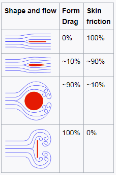
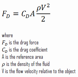
In fluid dynamics, drag is a force acting opposite to the relative motion of any moving object. The force a flowing fluid exerts on a body in the flow direction. Unlike other resistive forces, such as dry friction, which are nearly independent of velocity, drag forces depend on velocity. Drag force is proportional to the velocity for a laminar flow and the squared velocity for a turbulent flow. Drag is generally caused by two phenomena:

  • Drag - skin friction and form drag
    Source: wikipedia.org License: CC BY-SA 3.0

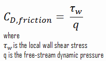
    Skin Friction.  In general, when a fluid flows over a stationary surface, e.g. the flat plate, the bed of a river, or the wall of a pipe, the fluid touching the surface is brought to rest by the shear stress to at the wall. The region in which flow adjusts from zero velocity at the wall to a maximum in the main stream of the flow is termed the boundary layer. Therefore, a moving fluid exerts tangential shear forces on the surface because of the no-slip condition caused by viscous effects.  This type of drag force, depends especially on the geometry, the roughness of the solid surface and on the type of fluid flow.

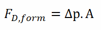
  • Form Drag. Form drag known also as pressure drag arises because of the shape and size of the object. This type of drag force is an interesting consequence the Bernoulli’s effect. According to Bernoulli’s principle, faster moving air exerts less pressure. This causes, that there can be a pressure difference between surfaces of the object. The general size and shape of the body are the most important factors in form drag. In general, bodies with a larger presented geometric cross-section will have a higher drag than thinner bodies.

Both of these forces, in general, have components in the direction of flow, and thus the resulting drag force is due to the combined effects of pressure and skin friction forces in the flow direction.

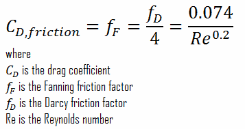
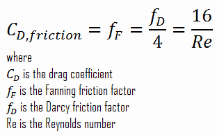
When the friction and pressure drag coefficients are available, the total drag coefficient is determined by simply adding them:

skin friction - form drag - coefficients

At low Reynolds numbers, most drag is due to friction drag. This is especially the case for highly streamlined bodies such as airfoils. On the other hand, at high Reynolds number, the pressure drop is significant, which increases form drag.

The components of the pressure and skin friction forces in the normal direction to flow tend to move the body in that direction, and their sum is called lift.

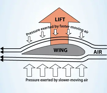
In aeronautics, the lift is an upward-acting force on an aircraft wing or airfoil. Bernoulli’s principle requires airfoil to be of an asymmetrical shape.

 
Bernoulli’s Principle – Lift Force
See also: Bernoulli’s Principle – Lift Force

Lift Force - Bernoulli PrincipleIn aeronautics, the lift is an upward-acting force on an aircraft wing or airfoil. Bernoulli’s principle requires airfoil to be of an asymmetrical shape. Its surface area must be greater on the top than on the bottom. As the air flows over the airfoil, it is displaced more by the top surface than the bottom. According to the continuity principle, this displacement must lead to an increase in flow velocity (resulting in a decrease in pressure). The flow velocity is increased some by the bottom airfoil surface, but considerably less than the flow on the top surface. The lift force of an airfoil, characterized by the lift coefficient, can be changed during the flight by changes in shape of an airfoil. The lift coefficient can thus be even doubled with relatively simple devices (flaps and slats) if used on the full span of the wing.
The use of Bernoulli’s principle may not be correct. The Bernoulli’s principle assumes incompressibility of the air, but in reality the air is easily compressible. But there are more limitations of explanations based on Bernoulli’s principle. There are two main popular explanations of lift:

  • Explanation based on downward deflection of the flow – Newton’s third law
  • Explanation based on changes in flow speed and pressure – Continuity principle and Bernoulli’s principle

Both explanations correctly identifies some aspects of the lift forces but leaves other important aspects of the phenomenon unexplained. A more comprehensive explanation involves both changes in flow speed and downward deflection and requires looking at the flow in more detail.

See more: Doug McLean, Understanding Aerodynamics: Arguing from the Real Physics. John Wiley & Sons Ltd. 2013. ISBN:  978-1119967514

What is Parasitic Drag
The term parasitic drag is mainly used in aerodynamics, since for lifting wings drag it is in general small compared to lift. Parasitic drag is a combination of form drag, skin friction drag and interference drag.
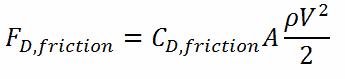
Skin Friction – Friction Drag

As was written, when a fluid flows over a stationary surface, e.g. the flat plate, the bed of a river, or the wall of a pipe, the fluid touching the surface is brought to rest by the shear stress to at the wall. The region in which flow adjusts from zero velocity at the wall to a maximum in the main stream of the flow is termed the boundary layer. Therefore, a moving fluid exerts tangential shear forces on the surface because of the no-slip condition caused by viscous effects. This type of drag force, depends especially on the geometry, the roughness of the solid surface (only in turbulent flow) and on the type of fluid flow. The friction drag is proportional to the surface area. Therefore, bodies with a larger surface area will experience a larger friction drag. This is why commercial airplanes reduce their total surface area to save fuel. Friction drag is a strong function of viscosity, and an “idealized” fluid with zero viscosity would produce zero friction drag since the wall shear stress would be zero.

Skin friction is caused by viscous drag in the boundary layer around the object. Basic characteristics of all laminar and turbulent boundary layers are shown in the developing flow over a flat plate. The stages of the formation of the boundary layer are shown in the figure below:

Boundary layer on flat plate

Boundary layers may be either laminar, or turbulent depending on the value of the Reynolds number.

For lower Reynolds numbers, the boundary layer is laminar and the streamwise velocity changes uniformly as one moves away from the wall, as shown on the left side of the figure. As the Reynolds number increases (with x) the flow becomes unstable and finally for higher Reynolds numbers, the boundary layer is turbulent and the streamwise velocity is characterized by unsteady (changing with time) swirling flows inside the boundary layer.

Transition from laminar to turbulent boundary layer occurs when Reynolds number at x exceeds Rex ~ 500,000. Transition may occur earlier, but it is dependent especially on the surface roughness. The turbulent boundary layer thickens more rapidly than the laminar boundary layer as a result of increased shear stress at the body surface.

There are two ways to decrease friction drag:

  • the first is to shape the moving body so that laminar flow is possible
  • the second method is to increase the length and decrease the cross-section of the moving object as much as practicable.

The skin friction coefficient, CD,friction, is defined by

skin friction - equation - drag coefficient

It must be noted, the skin friction coefficient is equal to the Fanning friction factor. The Fanning friction factor, named after John Thomas Fanning, is a dimensionless number, that is one-fourth of the Darcy friction factor. As can be seen, there is a connection between skin friction forces and frictional head losses.

See also: Darcy Friction Factor

For laminar flow in a pipe, the Fanning friction factor (skin friction coefficient) is a consequence of Poiseuille’s law that and it is given by following equations:

drag coefficient - laminar flow

In turbulent flows, however, things are more difficult, as the friction factor depends strongly on the pipe roughness. The friction factor for fluid flow can be determined using a Moody chart. For example:

drag coefficient - turbulent flow

The frictional component of the drag force is given by:

drag force - skin friction

Form Drag – Pressure Drag

form drag - pressure dragForm drag known also as pressure drag arises because of the shape and size of the object. The pressure drag is proportional to the difference between the pressures acting on the front and back of the immersed body, and the frontal area. This type of drag force is also an interesting consequence the Bernoulli’s effect. According to Bernoulli’s principle, faster moving air exerts less pressure. This causes, that there can be a pressure difference between surfaces of the object. The general size and shape of the body are the most important factors in form drag. In general, bodies with a larger presented geometric cross-section will have a higher drag than thinner bodies.

As can be seen from the figure, the drag force arises from the difference between the pressures acting on the front and back of the immersed body. For this force can be calculated (for this case) simply using the definition of pressure as:

form drag - drag force

Since the head loss is roughly proportional to the square of the flow rate in most engineering flows, the total drag coefficient can be determined by simply adding the friction and pressure drag coefficients:

skin friction - form drag - coefficients

Drag Force – Drag Equation

The drag force, FD,depends on the density of the fluid, the upstream velocity, and the size, shape, and orientation of the body, among other things. One way to express this is by means of the drag equation. The drag equation is a formula used to calculate the drag force experienced by an object due to movement through a fluid.

drag force - drag equation - formula

The reference area, A, is defined as the area of the orthographic projection of the object on a plane perpendicular to the direction of motion. For hollow objects, the reference area may be significantly larger than the cross sectional area, but for non-hollow objects, it is exactly the same as a cross sectional area.

Drag Coefficient – Drag Characteristics

As was written, the drag characteristics of a body is represented by the dimensionless drag coefficient, CD, defined as:

drag coefficient - characteristics

The reference area, A, is defined as the area of the orthographic projection of the object on a plane perpendicular to the direction of motion. For hollow objects, the reference area may be significantly larger than the cross sectional area, but for non-hollow objects, it is exactly the same as a cross sectional area. As can be seen, the drag coefficient is primarily a function of the shape of the body and taking into account both skin friction and form drag. It may also depend on the Reynolds number and the surface roughness.

When the friction and pressure drag coefficients are available, the total drag coefficient is determined by simply adding them:

skin friction - form drag - coefficients

At low Reynolds numbers, most drag is due to friction drag. This is especially the case for highly streamlined bodies such as airfoils. On the other hand, at high Reynolds number, the pressure drop is significant, which increases form drag.

 
Drag Coefficient - Cars
The drag coefficient is a common measure in automotive design. Drag coefficient, CD, is a commonly published rating of a car’s aerodynamic resistance, related to the shape of the car. Multiplying CD by the car’s frontal area gives an index of total drag. The result is called drag area.

Since aerodynamic drag and drag force increases with the square of velocity, this property becomes critically important at higher speeds. Reducing the drag coefficient in an automobile improves the performance of the vehicle as it pertains to speed and fuel efficiency. The average modern automobile achieves a drag coefficient of between CD = 0.30 and 0.35.

Drag Force in Nuclear Engineering

Analysis of the hydraulic lift force is one of the most important analysis in designing a fuel assembly and analyzing the hydraulic compatibility of mixed cores. The vertical forces are induced by upward high-velocity flow through the reactor core. The flow path for the reactor coolant through the reactor vessel would be:

  • Continuity Equation - Flow Rates through Reactor
    Example of flow rates in a reactor. It is an illustrative example, data do not represent any reactor design.

    The coolant enters the reactor vessel at the inlet nozzle and hits against the core barrel.

  • The core barrel forces the water to flow downward in the space between the reactor vessel wall and the core barrel, this space is usually known as the downcomer.
  • From the bottom of the pressure vessel, the flow is reversed up through the core in order to pass through the fuel assemblies, where the coolant temperature increases as it passes through the fuel rods.
  • Finally the hotter reactor coolant enters the upper internals region, where it is routed out the outlet nozzle into the hot legs of primary circuit and goes on to the steam generators.

Fuel assemblies are held by the upper guide structure assembly, which defines the top of the core. This assembly is made of stainless steel and has many purposes. The upper guide structure assembly exerts an axial force on fuel assemblies (through springs in the top nozzle), thus defines the exact position of the fuel assembly in the core. The upper guide structure assembly flange is held in place and preloaded by the RPV closure head flange. The upper guide structure assembly also guides and protects control rod assemblies and in-core instrumentation.

Required downforce of the upper guide structure assembly on fuel assemblies must very carefully calculated. Insufficient downforce can result in the lift of the fuel assembly, on the other hand, an excessive downforce can result in bowing of fuel assembly, which is also unacceptable.

Example: Drag Force – Drag Coefficient – Fuel Bundle

Hydraulic Diameter - Fuel ChannelCalculate the friction drag of a single fuel rod inside a reactor core at normal operation (design flow rate). Assume that this fuel rod is part of a fuel bundle with the rectangular fuel lattice and this fuel bundle does not contain spacing grids. Its height is h = 4m and the core flow velocity is constant and equal to Vcore = 5 m/s.

Assume that:

  • the outer diameter of the cladding is: d = 2 x rZr,1 = 9,3 mm
  • the pitch of fuel pins is: p = 13 mm
  • the relative roughness is ε/D = 5×10⁻⁴
  • the fluid density is: ρ = 714 kg/m3
  • the core flow velocity is constant and equal to Vcore = 5 m/s
  • the average temperature of reactor coolant is: Tbulk = 296°C

Calculation of the Reynolds number

To calculate the Reynolds number, we have to know:

  • the outer diameter of the cladding is: d = 2 x rZr,1 = 9,3 mm (to calculate the hydraulic diameter)
  • the pitch of fuel pins is: p = 13 mm  (to calculate the hydraulic diameter)
  • the dynamic viscosity of saturated water at 300°C is: μ = 0.0000859 N.s/m2
  • the fluid density is: ρ = 714 kg/m3

The hydraulic diameter, Dh, is a commonly used term when handling flow in non-circular tubes and channels. The hydraulic diameter of the fuel channel, Dh, is equal to 13,85 mm.

See also: Hydraulic Diameter

The Reynolds number inside the fuel channel is then equal to:

reynolds number - example

This fully satisfies the turbulent conditions.

Calculation of the Skin Friction Coefficient

The friction factor for turbulent flow depends strongly on the relative roughness. It is determined by the Colebrook equation or can be determined using the Moody chart. The Moody chart for Re = 575 600 and ε/D = 5 x 10⁻⁴ returns following values:

Therefore the skin friction coefficient is equal to:

skin friction coefficient - example

Calculation of the Drag Force

To calculate the drag force, we have to know:

  • the skin friction coefficient, which is: CD,friction = 0.00425
  • the area of pin surface, which is: A = π.d.h = 0.1169 m2
  • the fluid density, which is: ρ = 714 kg/m3
  • the core flow velocity, which is constant and equal to Vcore = 5 m/s

From the skin friction coefficient, which is equal to the Fanning friction factor we can calculate the frictional component of the drag force. The drag force is given by:

drag force - example

Assuming that a fuel assembly can have, for example, 289 fuel pins (17×17 fuel assembly), the frictional component of the drag force is then of the order of kilonewtons. Moreover, this drag force originates purely from the skin friction on fuel bundle. But typical PWR fuel assembly contains another components, which influence the fuel assembly hydraulics:

  • Fuel rods. Fuel rods contain the fuel and burnable poisons.
  • Top nozzle. Provides the mechanical support for the fuel assembly structure.
  • Bottom nozzle. Provides the mechanical support for the fuel assembly structure.
  • Spacing grid. Ensures an exact guiding of the fuel rods.
  • Guide thimble tube. Vacant tube for control rods or in-core instrumentation.

As was written, the second component of the drag force is the form drag. Form drag known also as pressure drag arises because of the shape and size of the object. The pressure drag is proportional to the difference between the pressures acting on the front and back of the immersed body, and the frontal area.

Pressure Drop – Fuel Assembly

In general, total fuel assembly pressure drop is formed by fuel bundle frictional drop (dependent on relative roughness of fuel rods, reynolds number, hydraulic diameter etc.) and other pressure drops of structural elements (top and bottom nozzle, spacing grids or mixing grids).

In general, it is not so simple to calculate pressure drops in fuel assemblies (especially the spacing grids) and it belongs to key know-how of certain fuel manufacturer. Mostly, pressure drops are measured in experimental hydraulic loops, rather than calculated.

Engineers use the pressure loss coefficient, PLC. It is noted K or ξ  (pronounced “xi”). This coefficient characterizes pressure loss of a certain hydraulic system or of a part of a hydraulic system. It can be easily measured in hydraulic loops. The pressure loss coefficient can be defined or measured for both straight pipes and especially for local (minor) losses.

PLC - Pressure loss coefficient - equations

Using data from above mentioned example, the pressure loss coefficient (only frictional from straight pipe) is equal to ξ = fDL/DH = 4.9. But the overall pressure loss coefficient (including spacing grids, top and bottom nozzles etc.) is usually about three times higher. This PLC (ξ = 4.9) causes that the pressure drop is of the order of (using the previous inputs) Δpfriction =  4.9 x 714 x 52/ 2 = 43.7 kPa (without spacing grids, top and bottom nozzles). About three times higher real PLC means about three times higher Δpfuel will be.

The overall reactor pressure loss, Δpreactor, must include:

  • downcomer and reactor bottom
  • lower support plate
  • fuel assembly including spacing grids, top and bottom nozzles and other structural components – Δpfuel
  • upper guide structure assembly

In result the overall reactor pressure loss – Δpreactor is usually of the order of hundreds kPa (let say 300 – 400 kPa) for design parameters.

 
References:
Reactor Physics and Thermal Hydraulics:
  1. J. R. Lamarsh, Introduction to Nuclear Reactor Theory, 2nd ed., Addison-Wesley, Reading, MA (1983).
  2. J. R. Lamarsh, A. J. Baratta, Introduction to Nuclear Engineering, 3d ed., Prentice-Hall, 2001, ISBN: 0-201-82498-1.
  3. W. M. Stacey, Nuclear Reactor Physics, John Wiley & Sons, 2001, ISBN: 0- 471-39127-1.
  4. Glasstone, Sesonske. Nuclear Reactor Engineering: Reactor Systems Engineering, Springer; 4th edition, 1994, ISBN: 978-0412985317
  5. Todreas Neil E., Kazimi Mujid S. Nuclear Systems Volume I: Thermal Hydraulic Fundamentals, Second Edition. CRC Press; 2 edition, 2012, ISBN: 978-0415802871
  6. Zohuri B., McDaniel P. Thermodynamics in Nuclear Power Plant Systems. Springer; 2015, ISBN: 978-3-319-13419-2
  7. Moran Michal J., Shapiro Howard N. Fundamentals of Engineering Thermodynamics, Fifth Edition, John Wiley & Sons, 2006, ISBN: 978-0-470-03037-0
  8. Kleinstreuer C. Modern Fluid Dynamics. Springer, 2010, ISBN 978-1-4020-8670-0.
  9. U.S. Department of Energy, THERMODYNAMICS, HEAT TRANSFER, AND FLUID FLOW. DOE Fundamentals Handbook, Volume 1, 2 and 3. June 1992.
  10. White Frank M., Fluid Mechanics, McGraw-Hill Education, 7th edition, February, 2010, ISBN: 978-0077422417

See also:

Fluid Dynamics

We hope, this article, Drag – Air and Fluid Resistance, helps you. If so, give us a like in the sidebar. Main purpose of this website is to help the public to learn some interesting and important information about thermal engineering.