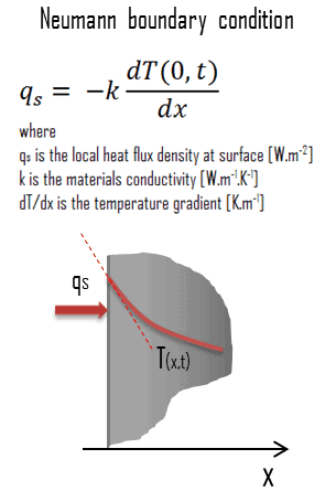
This article summarizes main types of Neumann boundary condition. Adiabatic boundary and thermal symmetry condition are often used in heat transfer problems. Thermal Engineering
Adiabatic Boundary – Thermal Symmetry
Adiabatic Boundary – Thermal Symmetry
Special Case – Adiabatic Boundary – Perfectly Insulated Boundary
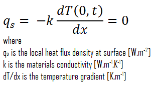
A special case of this condition corresponds to the perfectly insulated surface for which (∂T/∂x = 0). Heat transfer through a properly insulated surface can be taken to be zero since adequate insulation reduces heat transfer through a surface to negligible levels. Mathematically, this boundary condition can be expressed as:
Special Case – Thermal Symmetry
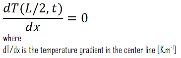
Another very important case, that can be used for solving heat transfer problems involving fuel rods, is the thermal symmetry. For example, the two surfaces of a large hot plate of thickness L suspended vertically in air will be subjected to the same thermal conditions, and thus the temperature distribution will be symmetrical (i.e. in one half of the plate will be the same temperature profile as that in the other half). As a result, there must be a maximum in in the center line of the plate and the center line can be viewed as an insulated surface (∂T/∂x = 0). The thermal condition at this plane of symmetry can be expressed as:
Fundamentals of Heat and Mass Transfer, 7th Edition. Theodore L. Bergman, Adrienne S. Lavine, Frank P. Incropera. John Wiley & Sons, Incorporated, 2011. ISBN: 9781118137253.
Heat and Mass Transfer. Yunus A. Cengel. McGraw-Hill Education, 2011. ISBN: 9780071077866.
Fundamentals of Heat and Mass Transfer. C. P. Kothandaraman. New Age International, 2006, ISBN: 9788122417722.
U.S. Department of Energy, Thermodynamics, Heat Transfer and Fluid Flow. DOE Fundamentals Handbook, Volume 2 of 3. May 2016.
Nuclear and Reactor Physics:
J. R. Lamarsh, Introduction to Nuclear Reactor Theory, 2nd ed., Addison-Wesley, Reading, MA (1983).
J. R. Lamarsh, A. J. Baratta, Introduction to Nuclear Engineering, 3d ed., Prentice-Hall, 2001, ISBN: 0-201-82498-1.
W. M. Stacey, Nuclear Reactor Physics, John Wiley & Sons, 2001, ISBN: 0- 471-39127-1.
Robert Reed Burn, Introduction to Nuclear Reactor Operation, 1988.
U.S. Department of Energy, Nuclear Physics and Reactor Theory. DOE Fundamentals Handbook, Volume 1 and 2. January 1993.
Paul Reuss, Neutron Physics. EDP Sciences, 2008. ISBN: 978-2759800414.
Advanced Reactor Physics:
K. O. Ott, W. A. Bezella, Introductory Nuclear Reactor Statics, American Nuclear Society, Revised edition (1989), 1989, ISBN: 0-894-48033-2.
K. O. Ott, R. J. Neuhold, Introductory Nuclear Reactor Dynamics, American Nuclear Society, 1985, ISBN: 0-894-48029-4.
D. L. Hetrick, Dynamics of Nuclear Reactors, American Nuclear Society, 1993, ISBN: 0-894-48453-2.
E. E. Lewis, W. F. Miller, Computational Methods of Neutron Transport, American Nuclear Society, 1993, ISBN: 0-894-48452-4.
See also:
Heat Equation
We hope, this article, Adiabatic Boundary – Thermal Symmetry, helps you. If so, give us a like in the sidebar. Main purpose of this website is to help the public to learn some interesting and important information about thermal engineering.
The general heat conduction equation in cylindrical coordinates can be obtained from an energy balance on a volume element in cylindrical coordinates. Thermal Engineering
Heat Equation in Cylindrical and Spherical Coordinates
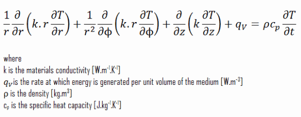
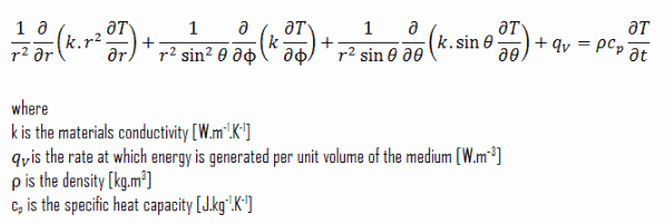
In engineering, there are plenty of problems, that cannot be solved in cartesian coordinates. Cylindrical and spherical systems are very common in thermal and especially in power engineering. The heat equation may also be expressed in cylindrical and spherical coordinates. The general heat conduction equation in cylindrical coordinates can be obtained from an energy balance on a volume element in cylindrical coordinates and using the Laplace operator, Δ, in the cylindrical and spherical form.
Cylindrical coordinates:
Spherical coordinates:
Obtaining analytical solutions to these differential equations requires a knowledge of the solution techniques of partial differential equations, which is beyond the scope of this text. On the other hand, there are many simplifications and assumptions, that can be applied to these equations and that lead to very important results. In the next section we limit our consideration to one-dimensional steady-state cases with constant thermal conductivity, since they result in ordinary differential equations.
References:
Heat Transfer:
Fundamentals of Heat and Mass Transfer, 7th Edition. Theodore L. Bergman, Adrienne S. Lavine, Frank P. Incropera. John Wiley & Sons, Incorporated, 2011. ISBN: 9781118137253.
Heat and Mass Transfer. Yunus A. Cengel. McGraw-Hill Education, 2011. ISBN: 9780071077866.
Fundamentals of Heat and Mass Transfer. C. P. Kothandaraman. New Age International, 2006, ISBN: 9788122417722.
U.S. Department of Energy, Thermodynamics, Heat Transfer and Fluid Flow. DOE Fundamentals Handbook, Volume 2 of 3. May 2016.
Nuclear and Reactor Physics:
J. R. Lamarsh, Introduction to Nuclear Reactor Theory, 2nd ed., Addison-Wesley, Reading, MA (1983).
J. R. Lamarsh, A. J. Baratta, Introduction to Nuclear Engineering, 3d ed., Prentice-Hall, 2001, ISBN: 0-201-82498-1.
W. M. Stacey, Nuclear Reactor Physics, John Wiley & Sons, 2001, ISBN: 0- 471-39127-1.
Robert Reed Burn, Introduction to Nuclear Reactor Operation, 1988.
U.S. Department of Energy, Nuclear Physics and Reactor Theory. DOE Fundamentals Handbook, Volume 1 and 2. January 1993.
Paul Reuss, Neutron Physics. EDP Sciences, 2008. ISBN: 978-2759800414.
Advanced Reactor Physics:
K. O. Ott, W. A. Bezella, Introductory Nuclear Reactor Statics, American Nuclear Society, Revised edition (1989), 1989, ISBN: 0-894-48033-2.
K. O. Ott, R. J. Neuhold, Introductory Nuclear Reactor Dynamics, American Nuclear Society, 1985, ISBN: 0-894-48029-4.
D. L. Hetrick, Dynamics of Nuclear Reactors, American Nuclear Society, 1993, ISBN: 0-894-48453-2.
E. E. Lewis, W. F. Miller, Computational Methods of Neutron Transport, American Nuclear Society, 1993, ISBN: 0-894-48452-4.
See also:
Thermal Conduction
We hope, this article, Heat Equation in Cylindrical and Spherical Coordinates, helps you. If so, give us a like in the sidebar. Main purpose of this website is to help the public to learn some interesting and important information about thermal engineering.
Conduction with Heat Generation – Solution of Heat Equation. In this article we will solve heat transfer problems in materials with internal source of heat. Thermal Engineering
Conduction with Heat Generation
Conduction with Heat Generation
In the preceding section we considered thermal conduction problems without internal heat sources. For these problems the temperature distribution in a medium was determined solely by conditions at the boundaries of the medium. But in engineering we can often meet a problem, in which internal heat sources are significant and determines the temperature distribution together with boundary conditions.
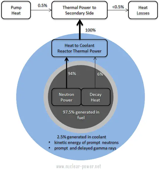
In nuclear engineering, these problems are of the highest importance, since most the heat generated in nuclear fuel is released inside the fuel pellets and the temperature distribution is determined primarily by heat generation distribution. Note that, as can be seen from the description of the individual components of the total energy energy released during the fission reaction, there is significant amount of energy generated outside the nuclear fuel (outside fuel rods). Especially the kinetic energy of prompt neutrons is largely generated in the coolant (moderator). This phenomena needs to be included in the nuclear calculations.
Thermal energy sources in power operation of pressurized water reactor
For LWR, it is generally accepted that about 2.5% of total energy is recovered in the moderator. This fraction of energy depends on the materials, their arrangement within the reactor, and thus on the reactor type.
Note that, heat generation is a volumetric phenomenon. That is, it occurs throughout the body of a medium. Therefore, the rate of heat generation in a medium is usually specified per unit volume and is denoted by gV [W/m3].
The temperature distribution and accordingly the heat flux is primarily determined by:
Geometry and boundary conditions. Different geometry leads to completely different temperature field.
Heat generation rate. The temperature drop through the body will increase with increased heat generation.
Thermal conductivity of the medium. Higher thermal conductivity will lead to lower temperature drop.
References:
Heat Transfer:
Fundamentals of Heat and Mass Transfer, 7th Edition. Theodore L. Bergman, Adrienne S. Lavine, Frank P. Incropera. John Wiley & Sons, Incorporated, 2011. ISBN: 9781118137253.
Heat and Mass Transfer. Yunus A. Cengel. McGraw-Hill Education, 2011. ISBN: 9780071077866.
Fundamentals of Heat and Mass Transfer. C. P. Kothandaraman. New Age International, 2006, ISBN: 9788122417722.
U.S. Department of Energy, Thermodynamics, Heat Transfer and Fluid Flow. DOE Fundamentals Handbook, Volume 2 of 3. May 2016.
Nuclear and Reactor Physics:
J. R. Lamarsh, Introduction to Nuclear Reactor Theory, 2nd ed., Addison-Wesley, Reading, MA (1983).
J. R. Lamarsh, A. J. Baratta, Introduction to Nuclear Engineering, 3d ed., Prentice-Hall, 2001, ISBN: 0-201-82498-1.
W. M. Stacey, Nuclear Reactor Physics, John Wiley & Sons, 2001, ISBN: 0- 471-39127-1.
Robert Reed Burn, Introduction to Nuclear Reactor Operation, 1988.
U.S. Department of Energy, Nuclear Physics and Reactor Theory. DOE Fundamentals Handbook, Volume 1 and 2. January 1993.
Paul Reuss, Neutron Physics. EDP Sciences, 2008. ISBN: 978-2759800414.
Advanced Reactor Physics:
K. O. Ott, W. A. Bezella, Introductory Nuclear Reactor Statics, American Nuclear Society, Revised edition (1989), 1989, ISBN: 0-894-48033-2.
K. O. Ott, R. J. Neuhold, Introductory Nuclear Reactor Dynamics, American Nuclear Society, 1985, ISBN: 0-894-48029-4.
D. L. Hetrick, Dynamics of Nuclear Reactors, American Nuclear Society, 1993, ISBN: 0-894-48453-2.
E. E. Lewis, W. F. Miller, Computational Methods of Neutron Transport, American Nuclear Society, 1993, ISBN: 0-894-48452-4.
See also:
Heat Equation
We hope, this article, Conduction with Heat Generation, helps you. If so, give us a like in the sidebar. Main purpose of this website is to help the public to learn some interesting and important information about thermal engineering.
Example of Heat Equation – Problem with Solution. In this article, there are two examples of solution of heat equation. Both examples are with solution. Thermal Engineering
Example of Heat Equation – Problem with Solution
Heat Conduction in a Large Plane Wall
Example of Heat Equation – Problem with Solution
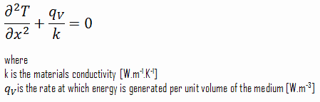
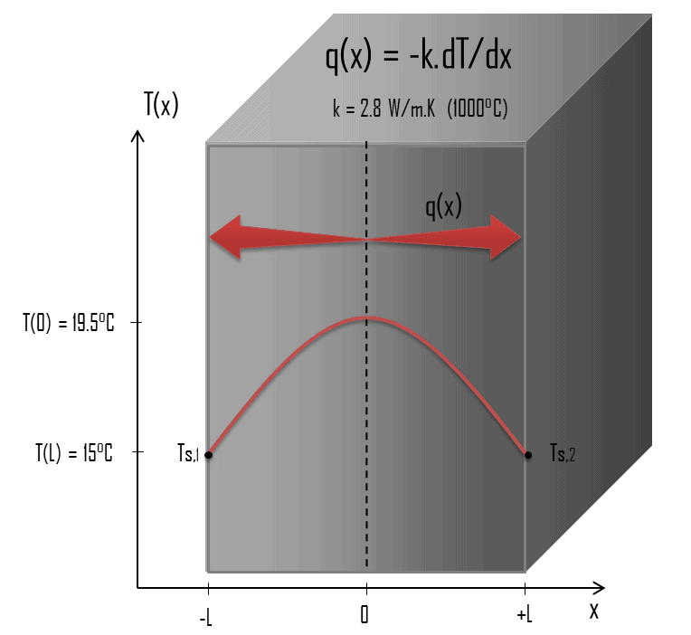
Consider the plane wall of thickness 2L, in which there is uniform and constant heat generation per unit volume, qV [W/m3]. The centre plane is taken as the origin for x and the slab extends to + L on the right and – L on the left. For constant thermal conductivity k, the appropriate form of the heat equation, is:
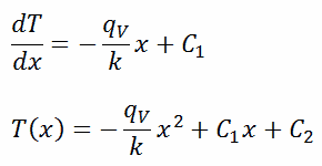
The general solution of this equation is:
where C1 and C2 are the constants of integration.
1)
Calculate the temperature distribution, T(x), through this thick plane wall, if:
the temperatures at both surfaces are 15.0°C
the thickness this wall is 2L = 10 mm.
the materials conductivity is k = 2.8 W/m.K (corresponds to uranium dioxide at 1000°C)
the volumetric heat rate is qV = 106 W/m3
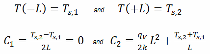
In this case, the surfaces are maintained at given temperatures Ts,1 and Ts,2. This corresponds to the Dirichlet boundary condition. Moreover, this problem is thermally symmetric and therefore we may use also thermal symmetry boundary condition. The constants may be evaluated using substitution into the general solution and are of the form:
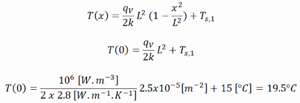
The resulting temperature distribution and the centerline (x = 0) temperature (maximum) in this plane wall at these specific boundary conditions will be:
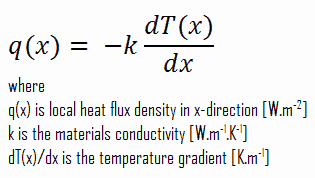
The heat flux at any point, qx [W.m-2], in the wall may, of course, be determined by using the temperature distribution and with the Fourier’s law. Note that, with heat generation the heat flux is no longer independent of x, the therefore:
Example of Heat Equation – Problem with Solution
Heat Conduction in a Fuel Rod
Most of PWRs use the uranium fuel, which is in the form of uranium dioxide. Uranium dioxide is a black semiconducting solid with very low thermal conductivity. On the other hand the uranium dioxide has very high melting point and has well known behavior. The UO2 is pressed into cylindrical pellets, these pellets are then sintered into the solid.
These cylindrical pellets are then loaded and encapsulated within a fuel rod (or fuel pin), which is made of zirconium alloys due to its very low absorption cross-section (unlike the stainless steel). The surface of the tube, which covers the pellets, is called fuel cladding.
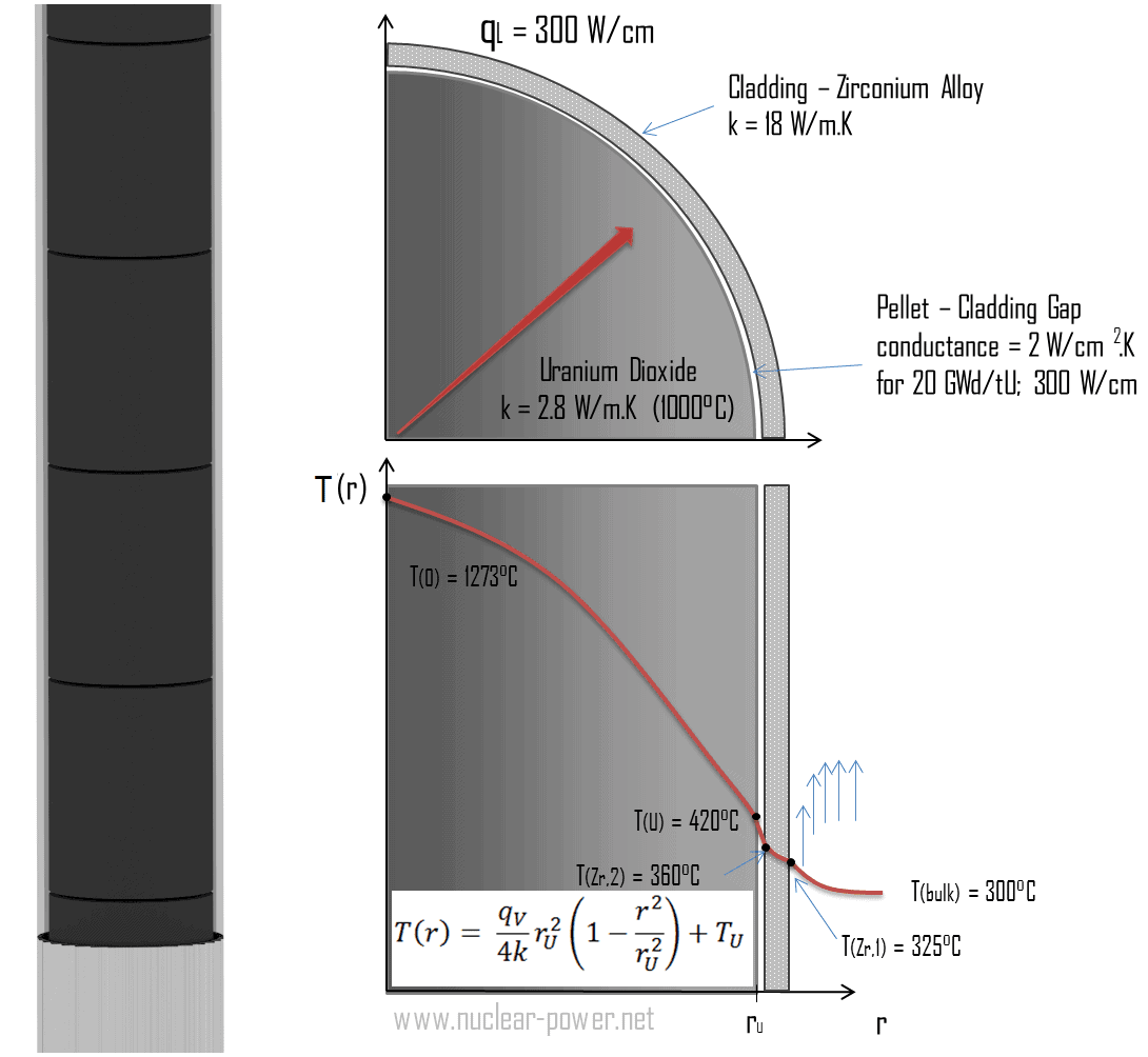
Thermal and mechanical behavior of fuel pellets and fuel rods constitute one of three key core design disciplines. Nuclear fuel is operated under very inhospitable conditions (thermal, radiation, mechanical) and must withstand more than normal conditions operation. For example temperatures in the centre of fuel pellets reach more than 1000°C (1832°F) accompanied by fission-gas releases. Therefore detailed knowledge of temperature distribution within a single fuel rod is essential for safe operation of nuclear fuel. In this section we will study heat conduction equation in cylindrical coordinates using Dirichlet boundary condition with given surface temperature (i.e. using Dirichlet boundary condition). Comprehensive analysis of fuel rod temperature profile will be studied in separate section.
Temperature in the centerline of a fuel pellet
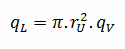
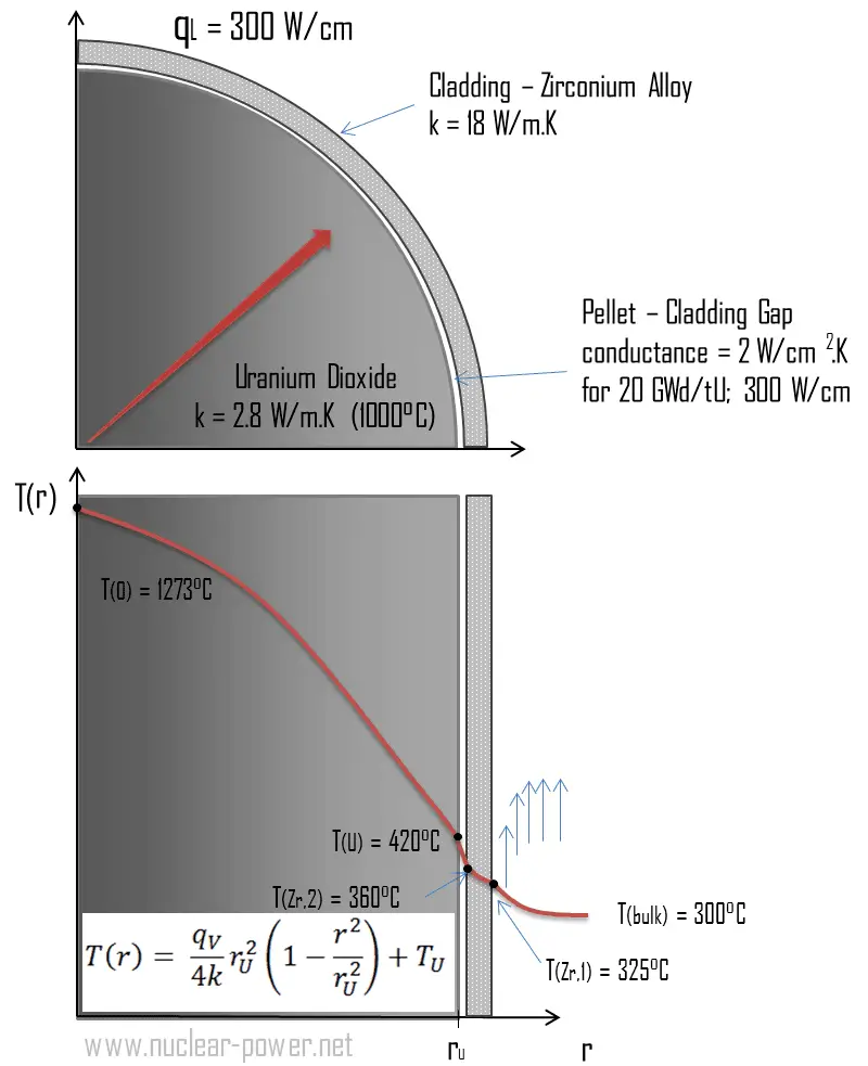
Consider the fuel pellet of radius rU = 0.40 cm, in which there is uniform and constant heat generation per unit volume, qV [W/m3]. Instead of volumetric heat rate qV [W/m3], engineers often use the linear heat rate, qL [W/m], which represents the heat rate of one meter of fuel rod. The linear heat rate can be calculated from the volumetric heat rate by:
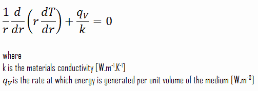
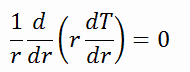
The centreline is taken as the origin for r-coordinate. Due to symmetry in z-direction and in azimuthal direction, we can separate of variables and simplify this problem to one-dimensional problem. Thus, we will solve for the temperature as function of radius, T(r), only. For constant thermal conductivity, k, the appropriate form of the cylindrical heat equation, is:
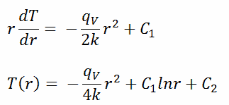
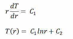
The general solution of this equation is:
where C1 and C2 are the constants of integration.
Calculate the temperature distribution, T(r), in this fuel pellet, if:
the temperatures at the surface of the fuel pellet is TU = 420°C
the fuel pellet radius rU = 4 mm.
the averaged material’s conductivity is k = 2.8 W/m.K (corresponds to uranium dioxide at 1000°C)
the linear heat rate is qL = 300 W/cm and thus the volumetric heat rate is qV = 597 x 106 W/m3
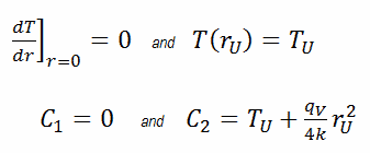
In this case, the surface is maintained at given temperatures TU. This corresponds to the Dirichlet boundary condition. Moreover, this problem is thermally symmetric and therefore we may use also thermal symmetry boundary condition. The constants may be evaluated using substitution into the general solution and are of the form:
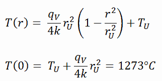
The resulting temperature distribution and the centerline (r = 0) temperature (maximum) in this cylindrical fuel pellet at these specific boundary conditions will be:
The radial heat flux at any radius, qr [W.m-1], in the cylinder may, of course, be determined by using the temperature distribution and with the Fourier’s law. Note that, with heat generation the heat flux is no longer independent of r.
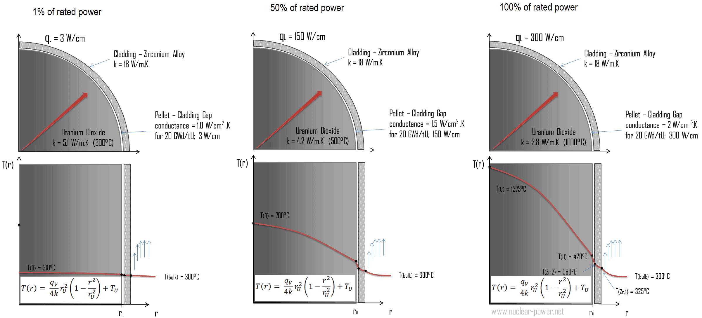
The following figure shows the temperature distribution in the fuel pellet at various power levels.
______
The temperature in an operating reactor varies from point to point within the system. As a consequence, there is always one fuel rod and one local volume, that are hotter than all the rest. In order to limit these hot places the peak power limits must be introduced. The peak power limits are associated with a boiling crisis and with the conditions which could cause fuel pellet melt. However, metallurgical considerations place an upper limits on the temperature of the fuel cladding and the fuel pellet. Above these temperatures there is a danger that the fuel may be damaged. One of the major objectives in the design of a nuclear reactors is to provide for the removal of the heat produced at the desired power level, while assuring that the maximum fuel temperature and the maximum cladding temperature are always below these predetermined values.
Temperature distribution in Fuel Cladding
Cladding is the outer layer of the fuel rods, standing between the reactor coolant and the nuclear fuel (i.e. fuel pellets). It is made of a corrosion-resistant material with low absorption cross section for thermal neutrons, usually zirconium alloy. Cladding prevents radioactive fission products from escaping the fuel matrix into the reactor coolant and contaminating it. Cladding constitute one of barriers in ‘defence-in-depth‘ approach.
Consider the fuel cladding of inner radius rZr,2 = 0.408 cm and outer radius rZr,1 = 0.465 cm. In comparison to fuel pellet, there is almost no heat generation in the fuel cladding (cladding is slightly heated by radiation). All heat generated in the fuel must be transferred via conduction through the cladding and therefore the inner surface is hotter than the outer surface.
To find the temperature distribution through the cladding we must solve the heat conduction equation. Due to symmetry in z-direction and in azimuthal direction, we can separate of variables and simplify this problem to one-dimensional problem. Thus, we will solve for the temperature as function of radius, T(r), only. In this example, we will assume that there is strictly no heat generation within the cladding. For constant thermal conductivity, k, the appropriate form of the cylindrical heat equation, is:
The general solution of this equation is:
where C1 and C2 are the constants of integration.
1)
Calculate the temperature distribution, T(r), in this fuel cladding, if:
the temperature at the inner surface of the cladding is TZr,2 = 360°C
the temperature of reactor coolant at this axial coordinate is Tbulk = 300°C
the heat transfer coefficient (convection; turbulent flow) is h = 41 kW/m2.K.
the averaged material’s conductivity is k = 18 W/m.K
the linear heat rate of the fuel is qL = 300 W/cm and thus the volumetric heat rate is qV = 597 x 106 W/m3
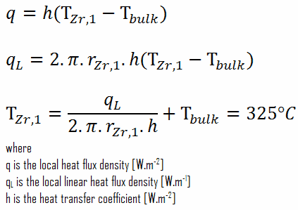
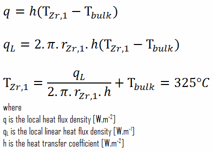
From the basic relationship for heat transfer by convection we can calculate the outer surface of the cladding as:
As can be seen, also in this case we have given surface temperatures TZr,1 and TZr,2. This corresponds to the Dirichlet boundary condition. The constants may be evaluated using substitution into the general solution and are of the form:
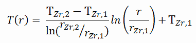
Solving for C1 and C2 and substituting into the general solution, we then obtain:
∆T – cladding surface – coolant
Detailed knowledge of geometry, outer radius of cladding, linear heat rate, convective heat transfer coefficient and the coolant temperature determines ∆T between the coolant (Tbulk) and the cladding surface (TZr,1). Therefore we can calculate the cladding surface temperature (TZr,1) simply using the Newton’s Law:
∆T in fuel cladding
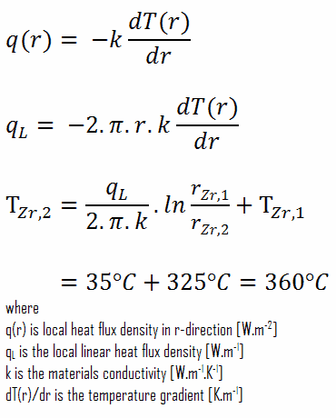
Detailed knowledge of geometry, outer and inner radius of cladding, linear heat rate, and the cladding surface temperature (TZr,1) determines ∆T between outer and inner surfaces of cladding. Therefore we can calculate the inner cladding surface temperature (TZr,2) simply using the Fourier’s Law:
References:
Heat Transfer:
Fundamentals of Heat and Mass Transfer, 7th Edition. Theodore L. Bergman, Adrienne S. Lavine, Frank P. Incropera. John Wiley & Sons, Incorporated, 2011. ISBN: 9781118137253.
Heat and Mass Transfer. Yunus A. Cengel. McGraw-Hill Education, 2011. ISBN: 9780071077866.
Fundamentals of Heat and Mass Transfer. C. P. Kothandaraman. New Age International, 2006, ISBN: 9788122417722.
U.S. Department of Energy, Thermodynamics, Heat Transfer and Fluid Flow. DOE Fundamentals Handbook, Volume 2 of 3. May 2016.
Nuclear and Reactor Physics:
J. R. Lamarsh, Introduction to Nuclear Reactor Theory, 2nd ed., Addison-Wesley, Reading, MA (1983).
J. R. Lamarsh, A. J. Baratta, Introduction to Nuclear Engineering, 3d ed., Prentice-Hall, 2001, ISBN: 0-201-82498-1.
W. M. Stacey, Nuclear Reactor Physics, John Wiley & Sons, 2001, ISBN: 0- 471-39127-1.
Robert Reed Burn, Introduction to Nuclear Reactor Operation, 1988.
U.S. Department of Energy, Nuclear Physics and Reactor Theory. DOE Fundamentals Handbook, Volume 1 and 2. January 1993.
Paul Reuss, Neutron Physics. EDP Sciences, 2008. ISBN: 978-2759800414.
Advanced Reactor Physics:
K. O. Ott, W. A. Bezella, Introductory Nuclear Reactor Statics, American Nuclear Society, Revised edition (1989), 1989, ISBN: 0-894-48033-2.
K. O. Ott, R. J. Neuhold, Introductory Nuclear Reactor Dynamics, American Nuclear Society, 1985, ISBN: 0-894-48029-4.
D. L. Hetrick, Dynamics of Nuclear Reactors, American Nuclear Society, 1993, ISBN: 0-894-48453-2.
E. E. Lewis, W. F. Miller, Computational Methods of Neutron Transport, American Nuclear Society, 1993, ISBN: 0-894-48452-4.
See also:
Heat Equation
We hope, this article, Example of Heat Equation – Problem with Solution, helps you. If so, give us a like in the sidebar. Main purpose of this website is to help the public to learn some interesting and important information about thermal engineering.
Heat Conduction in a Fuel Rod. Thermal and mechanical behavior of fuel pellets, or fuel rods, constitute one of three key core design disciplines. Thermal Engineering
Heat Conduction in a Fuel Rod
Heat Conduction in a Fuel Rod
Most of PWRs use the uranium fuel, which is in the form of uranium dioxide. Uranium dioxide is a black semiconducting solid with very low thermal conductivity. On the other hand the uranium dioxide has very high melting point and has well known behavior. The UO2 is pressed into cylindrical pellets, these pellets are then sintered into the solid.
These cylindrical pellets are then loaded and encapsulated within a fuel rod (or fuel pin), which is made of zirconium alloys due to its very low absorption cross-section (unlike the stainless steel). The surface of the tube, which covers the pellets, is called fuel cladding.
Thermal and mechanical behavior of fuel pellets and fuel rods constitute one of three key core design disciplines. Nuclear fuel is operated under very inhospitable conditions (thermal, radiation, mechanical) and must withstand more than normal conditions operation. For example temperatures in the centre of fuel pellets reach more than 1000°C (1832°F) accompanied by fission-gas releases. Therefore detailed knowledge of temperature distribution within a single fuel rod is essential for safe operation of nuclear fuel. In this section we will study heat conduction equation in cylindrical coordinates using Dirichlet boundary condition with given surface temperature (i.e. using Dirichlet boundary condition). Comprehensive analysis of fuel rod temperature profile will be studied in separate section.
Temperature in the centerline of a fuel pellet
Consider the fuel pellet of radius rU = 0.40 cm, in which there is uniform and constant heat generation per unit volume, qV [W/m3]. Instead of volumetric heat rate qV [W/m3], engineers often use the linear heat rate, qL [W/m], which represents the heat rate of one meter of fuel rod. The linear heat rate can be calculated from the volumetric heat rate by:
The centreline is taken as the origin for r-coordinate. Due to symmetry in z-direction and in azimuthal direction, we can separate of variables and simplify this problem to one-dimensional problem. Thus, we will solve for the temperature as function of radius, T(r), only. For constant thermal conductivity, k, the appropriate form of the cylindrical heat equation, is:
The general solution of this equation is:
where C1 and C2 are the constants of integration.
Calculate the temperature distribution, T(r), in this fuel pellet, if:
the temperatures at the surface of the fuel pellet is TU = 420°C
the fuel pellet radius rU = 4 mm.
the averaged material’s conductivity is k = 2.8 W/m.K (corresponds to uranium dioxide at 1000°C)
the linear heat rate is qL = 300 W/cm and thus the volumetric heat rate is qV = 597 x 106 W/m3
In this case, the surface is maintained at given temperatures TU. This corresponds to the Dirichlet boundary condition. Moreover, this problem is thermally symmetric and therefore we may use also thermal symmetry boundary condition. The constants may be evaluated using substitution into the general solution and are of the form:
The resulting temperature distribution and the centerline (r = 0) temperature (maximum) in this cylindrical fuel pellet at these specific boundary conditions will be:
The radial heat flux at any radius, qr [W.m-1], in the cylinder may, of course, be determined by using the temperature distribution and with the Fourier’s law. Note that, with heat generation the heat flux is no longer independent of r.
The following figure shows the temperature distribution in the fuel pellet at various power levels.
______
The temperature in an operating reactor varies from point to point within the system. As a consequence, there is always one fuel rod and one local volume, that are hotter than all the rest. In order to limit these hot places the peak power limits must be introduced. The peak power limits are associated with a boiling crisis and with the conditions which could cause fuel pellet melt. However, metallurgical considerations place an upper limits on the temperature of the fuel cladding and the fuel pellet. Above these temperatures there is a danger that the fuel may be damaged. One of the major objectives in the design of a nuclear reactors is to provide for the removal of the heat produced at the desired power level, while assuring that the maximum fuel temperature and the maximum cladding temperature are always below these predetermined values.
References:
Heat Transfer:
Fundamentals of Heat and Mass Transfer, 7th Edition. Theodore L. Bergman, Adrienne S. Lavine, Frank P. Incropera. John Wiley & Sons, Incorporated, 2011. ISBN: 9781118137253.
Heat and Mass Transfer. Yunus A. Cengel. McGraw-Hill Education, 2011. ISBN: 9780071077866.
Fundamentals of Heat and Mass Transfer. C. P. Kothandaraman. New Age International, 2006, ISBN: 9788122417722.
U.S. Department of Energy, Thermodynamics, Heat Transfer and Fluid Flow. DOE Fundamentals Handbook, Volume 2 of 3. May 2016.
Nuclear and Reactor Physics:
J. R. Lamarsh, Introduction to Nuclear Reactor Theory, 2nd ed., Addison-Wesley, Reading, MA (1983).
J. R. Lamarsh, A. J. Baratta, Introduction to Nuclear Engineering, 3d ed., Prentice-Hall, 2001, ISBN: 0-201-82498-1.
W. M. Stacey, Nuclear Reactor Physics, John Wiley & Sons, 2001, ISBN: 0- 471-39127-1.
Robert Reed Burn, Introduction to Nuclear Reactor Operation, 1988.
U.S. Department of Energy, Nuclear Physics and Reactor Theory. DOE Fundamentals Handbook, Volume 1 and 2. January 1993.
Paul Reuss, Neutron Physics. EDP Sciences, 2008. ISBN: 978-2759800414.
Advanced Reactor Physics:
K. O. Ott, W. A. Bezella, Introductory Nuclear Reactor Statics, American Nuclear Society, Revised edition (1989), 1989, ISBN: 0-894-48033-2.
K. O. Ott, R. J. Neuhold, Introductory Nuclear Reactor Dynamics, American Nuclear Society, 1985, ISBN: 0-894-48029-4.
D. L. Hetrick, Dynamics of Nuclear Reactors, American Nuclear Society, 1993, ISBN: 0-894-48453-2.
E. E. Lewis, W. F. Miller, Computational Methods of Neutron Transport, American Nuclear Society, 1993, ISBN: 0-894-48452-4.
See also:
Heat Equation
We hope, this article, Heat Conduction in a Fuel Rod, helps you. If so, give us a like in the sidebar. Main purpose of this website is to help the public to learn some interesting and important information about thermal engineering.
Heat Conduction in a Large Plane Wall. Consider the plane wall of thickness 2L, in which there is uniform and constant heat generation per unit volume, qV [W/m3]. Thermal Engineering
Heat Conduction in a Large Plane Wall
Heat Conduction in a Large Plane Wall
Consider the plane wall of thickness 2L, in which there is uniform and constant heat generation per unit volume, qV [W/m3]. The centre plane is taken as the origin for x and the slab extends to + L on the right and – L on the left. For constant thermal conductivity k, the appropriate form of the heat equation, is:
The general solution of this equation is:
where C1 and C2 are the constants of integration.
1)
Calculate the temperature distribution, T(x), through this thick plane wall, if:
the temperatures at both surfaces are 15.0°C
the thickness this wall is 2L = 10 mm.
the materials conductivity is k = 2.8 W/m.K (corresponds to uranium dioxide at 1000°C)
the volumetric heat rate is qV = 106 W/m3
In this case, the surfaces are maintained at given temperatures Ts,1 and Ts,2. This corresponds to the Dirichlet boundary condition. Moreover, this problem is thermally symmetric and therefore we may use also thermal symmetry boundary condition. The constants may be evaluated using substitution into the general solution and are of the form:
The resulting temperature distribution and the centerline (x = 0) temperature (maximum) in this plane wall at these specific boundary conditions will be:
The heat flux at any point, qx [W.m-2], in the wall may, of course, be determined by using the temperature distribution and with the Fourier’s law. Note that, with heat generation the heat flux is no longer independent of x, the therefore:
Example of Heat Equation – Problem with Solution
References:
Heat Transfer:
Fundamentals of Heat and Mass Transfer, 7th Edition. Theodore L. Bergman, Adrienne S. Lavine, Frank P. Incropera. John Wiley & Sons, Incorporated, 2011. ISBN: 9781118137253.
Heat and Mass Transfer. Yunus A. Cengel. McGraw-Hill Education, 2011. ISBN: 9780071077866.
Fundamentals of Heat and Mass Transfer. C. P. Kothandaraman. New Age International, 2006, ISBN: 9788122417722.
U.S. Department of Energy, Thermodynamics, Heat Transfer and Fluid Flow. DOE Fundamentals Handbook, Volume 2 of 3. May 2016.
Nuclear and Reactor Physics:
J. R. Lamarsh, Introduction to Nuclear Reactor Theory, 2nd ed., Addison-Wesley, Reading, MA (1983).
J. R. Lamarsh, A. J. Baratta, Introduction to Nuclear Engineering, 3d ed., Prentice-Hall, 2001, ISBN: 0-201-82498-1.
W. M. Stacey, Nuclear Reactor Physics, John Wiley & Sons, 2001, ISBN: 0- 471-39127-1.
Robert Reed Burn, Introduction to Nuclear Reactor Operation, 1988.
U.S. Department of Energy, Nuclear Physics and Reactor Theory. DOE Fundamentals Handbook, Volume 1 and 2. January 1993.
Paul Reuss, Neutron Physics. EDP Sciences, 2008. ISBN: 978-2759800414.
Advanced Reactor Physics:
K. O. Ott, W. A. Bezella, Introductory Nuclear Reactor Statics, American Nuclear Society, Revised edition (1989), 1989, ISBN: 0-894-48033-2.
K. O. Ott, R. J. Neuhold, Introductory Nuclear Reactor Dynamics, American Nuclear Society, 1985, ISBN: 0-894-48029-4.
D. L. Hetrick, Dynamics of Nuclear Reactors, American Nuclear Society, 1993, ISBN: 0-894-48453-2.
E. E. Lewis, W. F. Miller, Computational Methods of Neutron Transport, American Nuclear Society, 1993, ISBN: 0-894-48452-4.
See also:
Heat Equation
We hope, this article, Heat Conduction in a Large Plane Wall, helps you. If so, give us a like in the sidebar. Main purpose of this website is to help the public to learn some interesting and important information about thermal engineering.
Temperature distribution in Fuel Cladding. Cladding is the outer layer of the fuel rods, standing between the reactor coolant and the nuclear fuel (i.e. fuel pellets)
Temperature distribution in Fuel Cladding
Cladding is the outer layer of the fuel rods, standing between the reactor coolant and the nuclear fuel (i.e. fuel pellets). It is made of a corrosion-resistant material with low absorption cross section for thermal neutrons, usually zirconium alloy. Cladding prevents radioactive fission products from escaping the fuel matrix into the reactor coolant and contaminating it. Cladding constitute one of barriers in ‘defence-in-depth‘ approach.
Consider the fuel cladding of inner radius rZr,2 = 0.408 cm and outer radius rZr,1 = 0.465 cm. In comparison to fuel pellet, there is almost no heat generation in the fuel cladding (cladding is slightly heated by radiation). All heat generated in the fuel must be transferred via conduction through the cladding and therefore the inner surface is hotter than the outer surface.
To find the temperature distribution through the cladding we must solve the heat conduction equation. Due to symmetry in z-direction and in azimuthal direction, we can separate of variables and simplify this problem to one-dimensional problem. Thus, we will solve for the temperature as function of radius, T(r), only. In this example, we will assume that there is strictly no heat generation within the cladding. For constant thermal conductivity, k, the appropriate form of the cylindrical heat equation, is:
The general solution of this equation is:
where C1 and C2 are the constants of integration.
1)
Calculate the temperature distribution, T(r), in this fuel cladding, if:
the temperature at the inner surface of the cladding is TZr,2 = 360°C
the temperature of reactor coolant at this axial coordinate is Tbulk = 300°C
the heat transfer coefficient (convection; turbulent flow) is h = 41 kW/m2.K.
the averaged material’s conductivity is k = 18 W/m.K
the linear heat rate of the fuel is qL = 300 W/cm and thus the volumetric heat rate is qV = 597 x 106 W/m3
From the basic relationship for heat transfer by convection we can calculate the outer surface of the cladding as:
As can be seen, also in this case we have given surface temperatures TZr,1 and TZr,2. This corresponds to the Dirichlet boundary condition. The constants may be evaluated using substitution into the general solution and are of the form:
Solving for C1 and C2 and substituting into the general solution, we then obtain:
∆T – cladding surface – coolant
Detailed knowledge of geometry, outer radius of cladding, linear heat rate, convective heat transfer coefficient and the coolant temperature determines ∆T between the coolant (Tbulk) and the cladding surface (TZr,1). Therefore we can calculate the cladding surface temperature (TZr,1) simply using the Newton’s Law:
∆T in fuel cladding
Detailed knowledge of geometry, outer and inner radius of cladding, linear heat rate, and the cladding surface temperature (TZr,1) determines ∆T between outer and inner surfaces of cladding. Therefore we can calculate the inner cladding surface temperature (TZr,2) simply using the Fourier’s Law:
References:
Heat Transfer:
Fundamentals of Heat and Mass Transfer, 7th Edition. Theodore L. Bergman, Adrienne S. Lavine, Frank P. Incropera. John Wiley & Sons, Incorporated, 2011. ISBN: 9781118137253.
Heat and Mass Transfer. Yunus A. Cengel. McGraw-Hill Education, 2011. ISBN: 9780071077866.
Fundamentals of Heat and Mass Transfer. C. P. Kothandaraman. New Age International, 2006, ISBN: 9788122417722.
U.S. Department of Energy, Thermodynamics, Heat Transfer and Fluid Flow. DOE Fundamentals Handbook, Volume 2 of 3. May 2016.
Nuclear and Reactor Physics:
J. R. Lamarsh, Introduction to Nuclear Reactor Theory, 2nd ed., Addison-Wesley, Reading, MA (1983).
J. R. Lamarsh, A. J. Baratta, Introduction to Nuclear Engineering, 3d ed., Prentice-Hall, 2001, ISBN: 0-201-82498-1.
W. M. Stacey, Nuclear Reactor Physics, John Wiley & Sons, 2001, ISBN: 0- 471-39127-1.
Robert Reed Burn, Introduction to Nuclear Reactor Operation, 1988.
U.S. Department of Energy, Nuclear Physics and Reactor Theory. DOE Fundamentals Handbook, Volume 1 and 2. January 1993.
Paul Reuss, Neutron Physics. EDP Sciences, 2008. ISBN: 978-2759800414.
Advanced Reactor Physics:
K. O. Ott, W. A. Bezella, Introductory Nuclear Reactor Statics, American Nuclear Society, Revised edition (1989), 1989, ISBN: 0-894-48033-2.
K. O. Ott, R. J. Neuhold, Introductory Nuclear Reactor Dynamics, American Nuclear Society, 1985, ISBN: 0-894-48029-4.
D. L. Hetrick, Dynamics of Nuclear Reactors, American Nuclear Society, 1993, ISBN: 0-894-48453-2.
E. E. Lewis, W. F. Miller, Computational Methods of Neutron Transport, American Nuclear Society, 1993, ISBN: 0-894-48452-4.
See also:
Heat Equation
We hope, this article, Temperature distribution in Fuel Cladding, helps you. If so, give us a like in the sidebar. Main purpose of this website is to help the public to learn some interesting and important information about thermal engineering.
Critical Thickness of Insulation – Critical Radius. The thickness upto which heat flow increases and after which heat flow decreases is termed as critical thickness. In the case of cylinders and spheres it is called critical radius. Thermal Engineering
Critical Thickness of Insulation – Critical Radius
In a plane wall the area perpendicular to the direction of heat flow adding more insulation to a wall always decreases heat transfer. The thicker the insulation, the lower the heat transfer rate. This is due to the fact the outer surface have always the same area.
But in cylindrical and spherical coordinates, the addition of insulation also increases the outer surface, which decreases the convection resistance at the outer surface. Moreover, in some cases, a decrease in the convection resistance due to the increase in surface area can be more important than an increase in conduction resistance due to thicker insulation. As a result the total resistance may actually decrease resulting in increased heat flow.
The thickness upto which heat flow increases and after which heat flow decreases is termed as critical thickness. In the case of cylinders and spheres it is called critical radius. It can be derived the critical radius of insulation depends on the thermal conductivity of the insulation k and the external convection heat transfer coefficient h.
As can be seen, if r1 < rcr, as it is in this case, the total resistance decreases and the heat rate therefore increases with the addition of insulation. This trend continues until the outer radius of the insulation corresponds to the critical radius, where the heat rate reaches its maximum. This trend is desirable for cooling of an electrical wire, since the addition of electrical insulation would aid in transferring heat dissipated in the wire to the surroundings. On the other hand, any further addition of material (beyond rcr) would increase the total resistance and therefore decrease the heat loss. This behavior would be desirable for insulation of pipes, where insulation is added to reduce heat loss to the surroundings.
Example – Critical Thickness of Insulation
Assume a steel pipe of r1 = 10 mm, which is exposed to natural convection at h = 50 W/m2.K. This pipe is insulated by material of thermal conductivity k = 0.5 W/m.K. Determine the critical thickness of this combination:
Hence rcr > r1 and heat transfer will increase with the addition of insulation up to a thickness of rcr – r1 = (0.010 – 0.005)m = 0.005 m
Critical Thickness of Insulation – Spherical Coordinates
It can be shown in a similar manner that the critical radius of insulation for a spherical shell is:
References:
Heat Transfer:
Fundamentals of Heat and Mass Transfer, 7th Edition. Theodore L. Bergman, Adrienne S. Lavine, Frank P. Incropera. John Wiley & Sons, Incorporated, 2011. ISBN: 9781118137253.
Heat and Mass Transfer. Yunus A. Cengel. McGraw-Hill Education, 2011. ISBN: 9780071077866.
Fundamentals of Heat and Mass Transfer. C. P. Kothandaraman. New Age International, 2006, ISBN: 9788122417722.
U.S. Department of Energy, Thermodynamics, Heat Transfer and Fluid Flow. DOE Fundamentals Handbook, Volume 2 of 3. May 2016.
Nuclear and Reactor Physics:
J. R. Lamarsh, Introduction to Nuclear Reactor Theory, 2nd ed., Addison-Wesley, Reading, MA (1983).
J. R. Lamarsh, A. J. Baratta, Introduction to Nuclear Engineering, 3d ed., Prentice-Hall, 2001, ISBN: 0-201-82498-1.
W. M. Stacey, Nuclear Reactor Physics, John Wiley & Sons, 2001, ISBN: 0- 471-39127-1.
Robert Reed Burn, Introduction to Nuclear Reactor Operation, 1988.
U.S. Department of Energy, Nuclear Physics and Reactor Theory. DOE Fundamentals Handbook, Volume 1 and 2. January 1993.
Paul Reuss, Neutron Physics. EDP Sciences, 2008. ISBN: 978-2759800414.
Advanced Reactor Physics:
K. O. Ott, W. A. Bezella, Introductory Nuclear Reactor Statics, American Nuclear Society, Revised edition (1989), 1989, ISBN: 0-894-48033-2.
K. O. Ott, R. J. Neuhold, Introductory Nuclear Reactor Dynamics, American Nuclear Society, 1985, ISBN: 0-894-48029-4.
D. L. Hetrick, Dynamics of Nuclear Reactors, American Nuclear Society, 1993, ISBN: 0-894-48453-2.
E. E. Lewis, W. F. Miller, Computational Methods of Neutron Transport, American Nuclear Society, 1993, ISBN: 0-894-48452-4.
See also:
Heat Equation
We hope, this article, Critical Thickness of Insulation – Critical Radius, helps you. If so, give us a like in the sidebar. Main purpose of this website is to help the public to learn some interesting and important information about thermal engineering.
Navier-Stokes equations are equations, that describe the three-dimensional motion of viscous fluid. Navier-Stokes equations provide a very good approximation of reality. Thermal Engineering
Navier-Stokes Equations
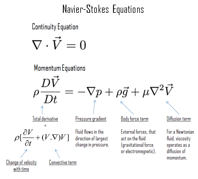
In fluid dynamics, the Navier-Stokes equations are equations, that describe the three-dimensional motion of viscous fluid substances. These equations are named after Claude-Louis Navier (1785-1836) and George Gabriel Stokes (1819-1903). In situations in which there are no strong temperature gradients in the fluid, these equations provide a very good approximation of reality.
The Navier-Stokes equations consists of a time-dependent continuity equation for conservation of mass, three time-dependent conservation of momentum equations and a time-dependent conservation of energy equation. There are four independent variables in the problem, the x, y, and z spatial coordinates of some domain, and the time t.
As can be seen, the Navier-Stokes equations are second-order nonlinear partial differential equations, their solutions have been found to a variety of interesting viscous flow problems. They may be used to model the weather, ocean currents, air flow around an airfoil and water flow in a pipe or in a reactor. The Navier–Stokes equations in their full and simplified forms help with the design of aircraft and cars, the study of blood flow, the design of nuclear reactors and many other things.
Solution of Navier-Stokes Equations
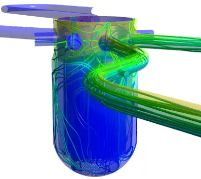
CFD numerical simulation Source: CFD development group – hzdr.de
Even though the Navier-Stokes equations have only a limited number of known analytical solutions, they are amenable to fine-gridded computer modeling. The main tool available for their analysis is CFD analysis. CFD is a branch of fluid mechanics that uses numerical analysis and algorithms to solve and analyze problems that involve turbulent fluid flows. It is widely accepted that the Navier–Stokes equations (or simplified Reynolds-averaged Navier–Stokes equations) are capable of exhibiting turbulent solutions, and these equations are the basis for essentially all CFD codes. It is possible now to achieve approximate, but realistic, CFD results for a wide variety of complex two- and three-dimensional viscous flows.
The Navier–Stokes equations are also of great interest in a purely mathematical sense. Unfortunately, the highly intermittent and irregular character of turbulent flowcomplicates all analyses. It has not yet been proven that in three dimensions solutions always exist, or that if they do exist, then they are smooth. In fact, general solution of the Navier-Stokes equations with turbulences is often said to be the “last unsolved problem in classical mathemetical physics.”
Characteristics of Turbulent Flow
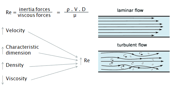
Turbulent flow tends to occur at higher velocities, low viscosity and at higher characteristic linear dimensions.
If the Reynolds number is greater than Re > 3500, the flow is turbulent.
Irregularity: The flow is characterized by the irregular movement of particles of the fluid. The movement of fluid particles is chaotic. For this reason, turbulent flow is normally treated statistically rather than deterministically.
Diffusivity: In turbulent flow, a fairly flat velocity distribution exists across the section of pipe, with the result that the entire fluid flows at a given single value and drops rapidly extremely close to the walls. The characteristic which is responsible for the enhanced mixing and increased rates of mass, momentum and energy transports in a flow is called “diffusivity”.
Rotationality: Turbulent flow is characterized by a strong three-dimensional vortex generation mechanism. This mechanism is known as vortex stretching.
Dissipation: A dissipative process is a process in which the kinetic energy of turbulent flow is transformed into internal energy by viscous shear stress.
Kolmogorov Microscales
In the view of Kolmogorov (Andrey Nikolaevich Kolmogorov was a Russian mathematician who made significant contributions to the mathematics of probability theory and turbulence), turbulent motions involve a wide range of scales. From a macroscale at which the energy is supplied, to a microscale at which energy is dissipated by viscosity.
For example, consider a cumulus cloud. The macroscale of the cloud can be of the order of kilometers and may grow or persist over long periods of time. Within the cloud, eddies may occur over scales of the order of millimeters. For smaller flows such as in pipes, the microscales may be much smaller. Most of the kinetic energy of the turbulent flow is contained in the macroscale structures. The energy “cascades” from these macroscale structures to microscale structures by an inertial mechanism. This process is known as the turbulent energy cascade.
The smallest scales in turbulent flow are known as the Kolmogorov microscales. These are small enough that molecular diffusion becomes important and viscous dissipation of energy takes place and the turbulent kinetic energy is dissipated into heat.
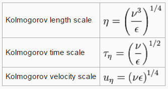
The smallest scales in turbulent flow, i.e. the Kolmogorov microscales are:
where ε is the average rate of dissipation rate of turbulence kinetic energy per unit mass and has dimensions (m2/s3). ν is the kinematic viscosity of the fluid and has dimensions (m2/s).
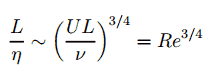
The size of the smallest eddy in the flow is determined by viscosity. The Kolmogorov length scale decreases as viscosity decreases. For very high Reynolds number flows, the viscous forces are smaller with respect to inertial forces. Smaller scale motions are then necessarily generated until the effects of viscosity become important and energy is dissipated. The ratio of largest to smallest length scales in the turbulent flow are proportional to the Reynolds number (raises with the three-quarters power).
This causes direct numerical simulations of turbulent flow to be practically impossible. For example, consider a flow with a Reynolds number of 106. In this case the ratio L/l is proportional to 1018/4. Since we have to analyze three-dimensional problem, we need to compute a grid that consisted of at least 1014 grid points. This far exceeds the capacity and possibilities of existing computers.
References:
Reactor Physics and Thermal Hydraulics:
J. R. Lamarsh, Introduction to Nuclear Reactor Theory, 2nd ed., Addison-Wesley, Reading, MA (1983).
J. R. Lamarsh, A. J. Baratta, Introduction to Nuclear Engineering, 3d ed., Prentice-Hall, 2001, ISBN: 0-201-82498-1.
W. M. Stacey, Nuclear Reactor Physics, John Wiley & Sons, 2001, ISBN: 0- 471-39127-1.
Todreas Neil E., Kazimi Mujid S. Nuclear Systems Volume I: Thermal Hydraulic Fundamentals, Second Edition. CRC Press; 2 edition, 2012, ISBN: 978-0415802871
Zohuri B., McDaniel P. Thermodynamics in Nuclear Power Plant Systems. Springer; 2015, ISBN: 978-3-319-13419-2
Moran Michal J., Shapiro Howard N. Fundamentals of Engineering Thermodynamics, Fifth Edition, John Wiley & Sons, 2006, ISBN: 978-0-470-03037-0
Kleinstreuer C. Modern Fluid Dynamics. Springer, 2010, ISBN 978-1-4020-8670-0.
U.S. Department of Energy, THERMODYNAMICS, HEAT TRANSFER, AND FLUID FLOW. DOE Fundamentals Handbook, Volume 1, 2 and 3. June 1992.
White Frank M., Fluid Mechanics, McGraw-Hill Education, 7th edition, February, 2010, ISBN: 978-0077422417
See also:
Fluid Dynamics
We hope, this article, Navier-Stokes Equation, helps you. If so, give us a like in the sidebar. Main purpose of this website is to help the public to learn some interesting and important information about thermal engineering.
Even though the Navier-Stokes equations have only a limited number of known analytical solutions, they are amenable to fine-gridded computer modeling. Solution of Navier-Stokes Equations
Solution of Navier-Stokes Equations
CFD numerical simulation Source: CFD development group – hzdr.de
Even though the Navier-Stokes equations have only a limited number of known analytical solutions, they are amenable to fine-gridded computer modeling. The main tool available for their analysis is CFD analysis. CFD is a branch of fluid mechanics that uses numerical analysis and algorithms to solve and analyze problems that involve turbulent fluid flows. It is widely accepted that the Navier–Stokes equations (or simplified Reynolds-averaged Navier–Stokes equations) are capable of exhibiting turbulent solutions, and these equations are the basis for essentially all CFD codes. It is possible now to achieve approximate, but realistic, CFD results for a wide variety of complex two- and three-dimensional viscous flows.
The Navier–Stokes equations are also of great interest in a purely mathematical sense. Unfortunately, the highly intermittent and irregular character of turbulent flowcomplicates all analyses. It has not yet been proven that in three dimensions solutions always exist, or that if they do exist, then they are smooth. In fact, general solution of the Navier-Stokes equations with turbulences is often said to be the “last unsolved problem in classical mathemetical physics.”
References:
Reactor Physics and Thermal Hydraulics:
J. R. Lamarsh, Introduction to Nuclear Reactor Theory, 2nd ed., Addison-Wesley, Reading, MA (1983).
J. R. Lamarsh, A. J. Baratta, Introduction to Nuclear Engineering, 3d ed., Prentice-Hall, 2001, ISBN: 0-201-82498-1.
W. M. Stacey, Nuclear Reactor Physics, John Wiley & Sons, 2001, ISBN: 0- 471-39127-1.
Todreas Neil E., Kazimi Mujid S. Nuclear Systems Volume I: Thermal Hydraulic Fundamentals, Second Edition. CRC Press; 2 edition, 2012, ISBN: 978-0415802871
Zohuri B., McDaniel P. Thermodynamics in Nuclear Power Plant Systems. Springer; 2015, ISBN: 978-3-319-13419-2
Moran Michal J., Shapiro Howard N. Fundamentals of Engineering Thermodynamics, Fifth Edition, John Wiley & Sons, 2006, ISBN: 978-0-470-03037-0
Kleinstreuer C. Modern Fluid Dynamics. Springer, 2010, ISBN 978-1-4020-8670-0.
U.S. Department of Energy, THERMODYNAMICS, HEAT TRANSFER, AND FLUID FLOW. DOE Fundamentals Handbook, Volume 1, 2 and 3. June 1992.
White Frank M., Fluid Mechanics, McGraw-Hill Education, 7th edition, February, 2010, ISBN: 978-0077422417
See also:
Navier-Stokes Equations
We hope, this article, Solution of Navier-Stokes Equation, helps you. If so, give us a like in the sidebar. Main purpose of this website is to help the public to learn some interesting and important information about thermal engineering.
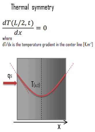 Another very important case, that can be used for solving heat transfer problems involving fuel rods, is the thermal symmetry. For example, the two surfaces of a large hot plate of thickness L suspended vertically in air will be subjected to the same thermal conditions, and thus the temperature distribution will be symmetrical (i.e. in one half of the plate will be the same temperature profile as that in the other half). As a result, there must be a maximum in in the center line of the plate and the center line can be viewed as an insulated surface (∂T/∂x = 0). The thermal condition at this plane of symmetry can be expressed as: