Properties of Insulation Materials
Thermal insulation is based on the use of substances with very low thermal conductivity and low surface emissivity. It is important to note that the factors influencing performance may vary over time as material ages or environmental conditions change. Key properties of insulation materials are:
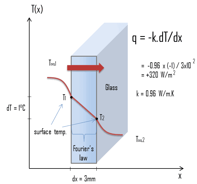
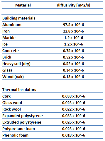
- Thermal Conductivity. Thermal conductivity, measured in W/mK describes how well a material conducts heat. Note that Fourier’s law applies for all matter, regardless of its state (solid, liquid, or gas), therefore, it is also defined for liquids and gases. It is the amount of heat (in watts) transferred through a square area of material of given thickness (in metres) due to a difference in temperature. The lower the thermal conductivity of the material the greater the material’s ability to resist heat transfer, and hence the greater the insulation’s effectiveness. In general, gases have a low thermal conductivity (e.g. air has 0.025 W/mK) whilst metals has a high values (e.g. copper has 400 W/mK). Commonly used insulants tend to have a thermal conductivity between 0.019 W/mK and 0.046 W/mK.
- R-Value – Thermal Resistance. R-value (thermal insulance factor) is a measure of thermal resistance. The higher the R-value, the greater the insulating effectiveness. Thermal insulance has the units [(m2.K)/W] in SI units or [(ft2·°F·hr)/Btu] in imperial units. It is the thermal resistance of unit area of a material. The R-value depends on the type of insulation, its thickness, and its density. An area and a temperature difference is required to solve for heat transferred. The construction industry makes use of units such as the R-value (resistance), which is expressed as the thickness of the material normalized to the thermal conductivity, and under uniform conditions it is the ratio of the temperature difference across an insulator and the heat flux density through it: R(x) = ∆T/q. The higher the R-value, the more a material prevents heat transfer. As can be seen, the resistance is dependent on the thickness of the product.
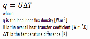
- U-value – Thermal Transmittance. Thermal Transmittance describes how well the material conducts heat. Thermal Transmittance is the inverse of the R-value (i.e. 1/R) and the lower the U-value the better the insulation. The U-value is defined by an expression analogous to Newton’s law of cooling.
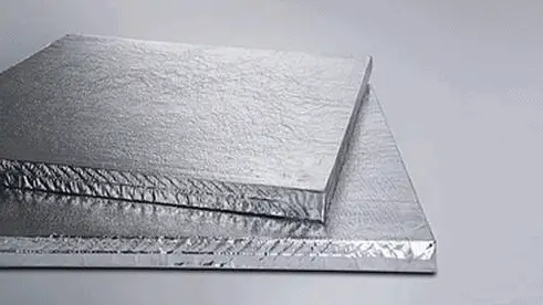
- Surface Emissivity. As was written, heat transfer through any of these insulation systems may include several modes: conduction through the solid materials, conduction or convection through the air in the void spaces and radiation exchange between the surfaces of the solid matrix. Therefore the emissivity of a material plays also very important role. The emissivity, ε, of the surface of a material is its effectiveness in emitting energy as thermal radiation and varies between 0.0 and 1.0. Emissivity is simply a factor by which we multiply the black body heat transfer to take into account that the black body is the ideal case. The surface of a blackbody emits thermal radiation at the rate of approximately 448 watts per square metre at room temperature (25 °C, 298.15 K). Real objects with emissivities less than 1.0 (e.g. aluminium foil) emit radiation at correspondingly lower rates (e.g. 448 x 0.07 = 31.4 W/m2).
- Fire resisitance. Thermal insulating materials must have a fire resistance classification. This classification is important because it can be of influence on the application of insulating materials. Normally the fire resistance classification is followed by as a time limit in minutes 15, 30, 45, 60, 90, 120, 180, 240, or 360 which shows the time the performance criteria is fulfilled during a standardized fire test.
Insulation Materials
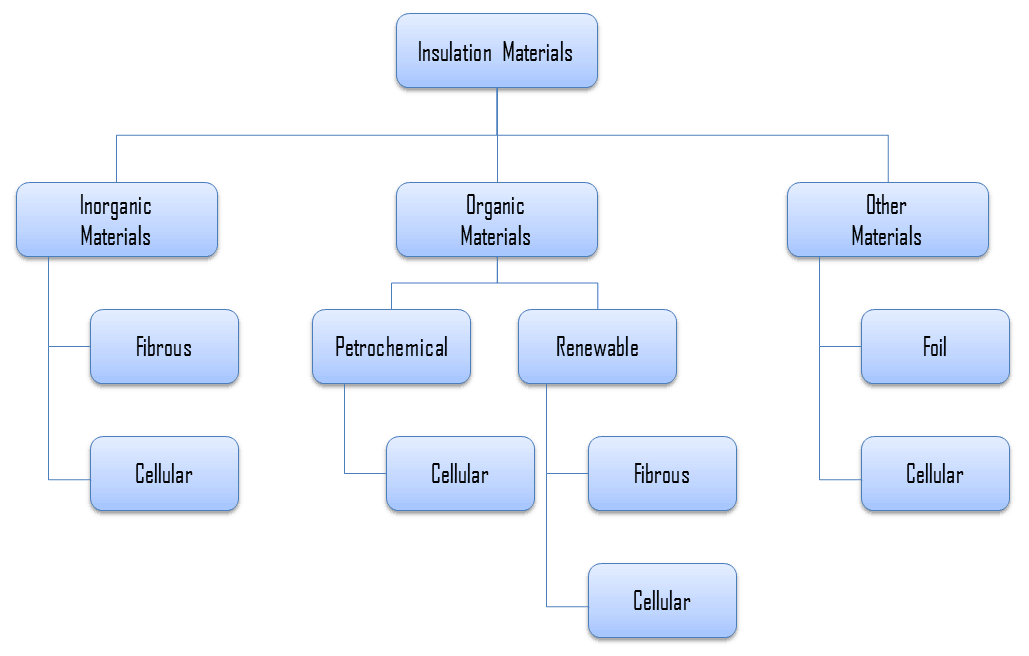
 As was written, thermal insulation is based on the use of substances with very low thermal conductivity. These materials are known as insulation materials. Common insulation materials are wool, fiberglass, rock wool, polystyrene, polyurethane, and goose feather etc. These materials are very poor conductors of heat and are therefore good thermal insulators.
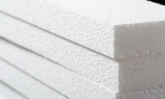
It must be added, thermal insulation is primarily based on the very low thermal conductivity of gases. Gases possess poor thermal conduction properties compared to liquids and solids, and thus makes a good insulation material if they can be trapped (e.g. in a foam-like structure). Air and other gases are generally good insulators. But the main benefit is in the absence of convection. Therefore, many insulation materials (e.g.polystyrene) function simply by having a large number of gas-filled pockets which prevent large-scale convection. In all types of thermal insulation, evacuation of the air in the void space will further reduce the overall thermal conductivity of the insulator.
Alternation of gas pocket and solid material causes that the heat must be transferred through many interfaces causing rapid decrease in heat transfer coefficient.
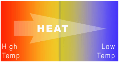
It must be noted, heat losses from hotter objects occurs by three mechanisms (either individually or in combination):
So far we have not discussed thermal radiation as a mode of heat losses. Radiation heat transfer is mediated by electromagnetic radiation and therefore it does not require any medium for heat transfer. In fact, energy transfer by radiation is fastest (at the speed of light) and it suffers no attenuation in a vacuum. Any material that has a temperature above absolute zero gives off some radiant energy. Most energy of this type is in the infra-red region of the electromagnetic spectrum although some of it is in the visible region. In order to decrease this type of heat transfer, materials with low emissivity (high reflectivity) should be used. Reflective insulations are usually composed of multilayered, parallel foils of high reflectivity, which are spaced to reflect thermal radiation back to its source. The emissivity, ε, of the surface of a material is its effectiveness in emitting energy as thermal radiation and varies between 0.0 and 1.0. In general, polished metals have very low emissivity and therefore are widely used to reflect radiant energy back to its source as in case of first aid blankets.
Critical Thickness of Insulation
 In a plane wall the area perpendicular to the direction of heat flow adding more insulation to a wall always decreases heat transfer. The thicker the insulation, the lower the heat transfer rate. This is due to the fact the outer surface have always the same area.
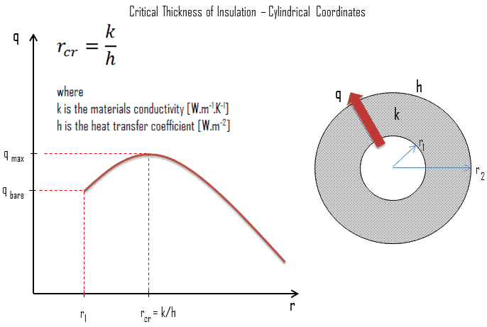
But in cylindrical and spherical coordinates, the addition of insulation also increases the outer surface, which decreases the convection resistance at the outer surface. Moreover, in some cases, a decrease in the convection resistance due to the increase in surface area can be more important than an increase in conduction resistance due to thicker insulation. As a result the total resistance may actually decrease resulting in increased heat flow.
The thickness upto which heat flow increases and after which heat flow decreases is termed as critical thickness. In the case of cylinders and spheres it is called critical radius. It can be derived the critical radius of insulation depends on the thermal conductivity of the insulation k and the external convection heat transfer coefficient h.
See also: Critical radius of insulation
Example – Heat Loss through a Wall
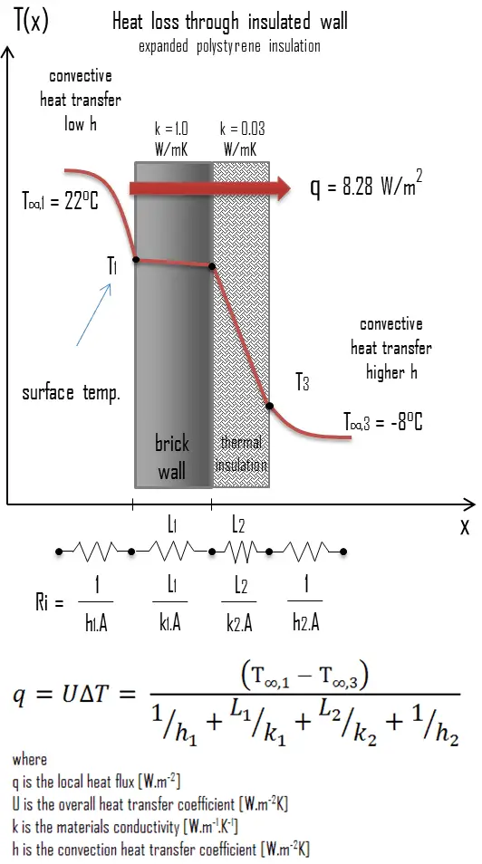
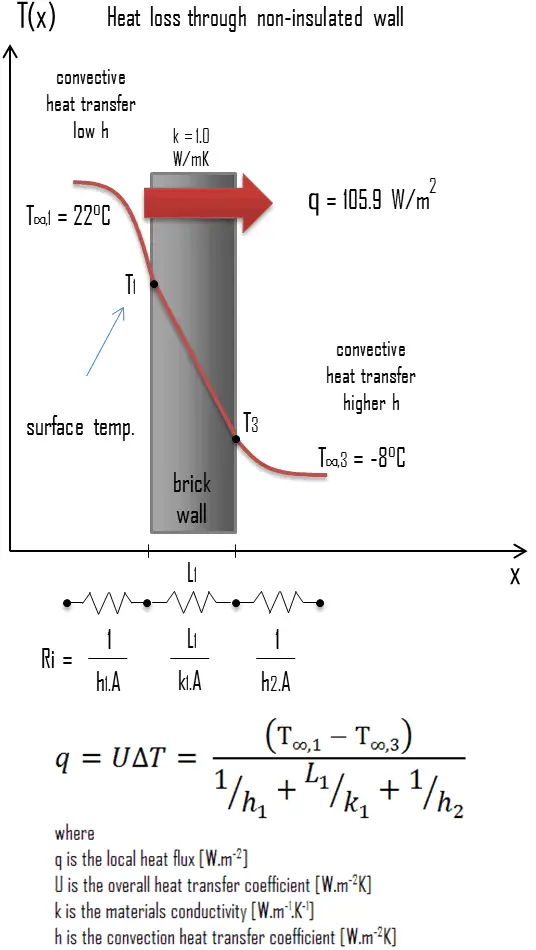 A major source of heat loss from a house is through walls. Calculate the rate of heat flux through a wall 3 m x 10 m in area (A = 30 m2). The wall is 15 cm thick (L1) and it is made of bricks with the thermal conductivity of k1 = 1.0 W/m.K (poor thermal insulator). Assume that, the indoor and the outdoor temperatures are 22°C and -8°C, and the convection heat transfer coefficients on the inner and the outer sides are h1 = 10 W/m2K and h2 = 30 W/m2K, respectively. Note that, these convection coefficients strongly depend especially on ambient and interior conditions (wind, humidity, etc.).
- Calculate the heat flux (heat loss) through this non-insulated wall.
- Now assume thermal insulation on the outer side of this wall. Use expanded polystyrene insulation 10 cm thick (L2) with the thermal conductivity of k2 = 0.03 W/m.K and calculate the heat flux (heat loss) through this composite wall.
Solution:
As was written, many of the heat transfer processes involve composite systems and even involve a combination of both conduction and convection. With these composite systems, it is often convenient to work with an overall heat transfer coefficient, known as a U-factor. The U-factor is defined by an expression analogous to Newton’s law of cooling:
The overall heat transfer coefficient is related to the total thermal resistance and depends on the geometry of the problem.
- bare wall
Assuming one-dimensional heat transfer through the plane wall and disregarding radiation, the overall heat transfer coefficient can be calculated as:
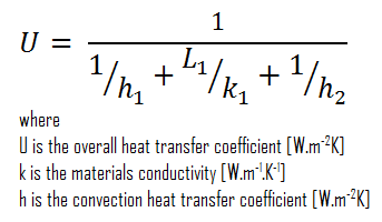
The overall heat transfer coefficient is then:
U = 1 / (1/10 + 0.15/1 + 1/30) = 3.53 W/m2K
The heat flux can be then calculated simply as:
q = 3.53 [W/m2K] x 30 [K] = 105.9 W/m2
The total heat loss through this wall will be:
qloss = q . A = 105.9 [W/m2] x 30 [m2] = 3177W
- composite wall with thermal insulation
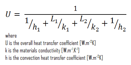
Assuming one-dimensional heat transfer through the plane composite wall, no thermal contact resistance and disregarding radiation, the overall heat transfer coefficient can be calculated as:
 The overall heat transfer coefficient is then:
U = 1 / (1/10 + 0.15/1 + 0.1/0.03 + 1/30) = 0.276 W/m2K
The heat flux can be then calculated simply as:
q = 0.276 [W/m2K] x 30 [K] = 8.28 W/m2
The total heat loss through this wall will be:
qloss = q . A = 8.28 [W/m2] x 30 [m2] = 248 W
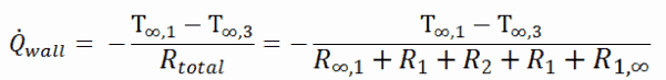
As can be seen, an addition of thermal insulator causes significant decrease in heat losses. It must be added, an addition of next layer of thermal insulator does not cause such high savings. This can be better seen from the thermal resistance method, which can be used to calculate the heat transfer through composite walls. The rate of steady heat transfer between two surfaces is equal to the temperature difference divided by the total thermal resistance between those two surfaces.
We hope, this article, Main Property of Insulation Materials, helps you. If so, give us a like in the sidebar. Main purpose of this website is to help the public to learn some interesting and important information about thermal engineering.