Facebook Instagram Youtube Twitter

What is Blackbody – Definition

A blackbody is an idealized physical body, that has specific properties. By definition, a blackbody in thermal equilibrium has an emissivity of ε = 1.0. Thermal Engineering

Blackbody Radiation

It is known that the amount of radiation energy emitted from a surface at a given wavelength depends on the material of the body and the condition of its surface as well as the surface temperature. Therefore, various materials emit different amounts of radiant energy even whhen they are at the same temperature. A body that emits the maximum amount of heat for its absolute temperature is called a blackbody.
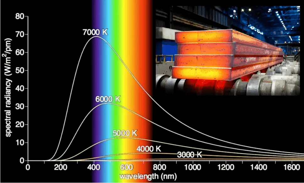
blackbody radiationA blackbody is an idealized physical body, that has specific properties. By definition, a black body in thermal equilibrium has an emissivity of ε = 1.0. Real objects do not radiate as much heat as a perfect black body. They radiate less heat than a black body and therefore are called gray bodies.

The surface of a blackbody emits thermal radiation at the rate of approximately 448 watts per square metre at room temperature (25 °C, 298.15 K). Real objects with emissivities less than 1.0 (e.g. copper wire) emit radiation at correspondingly lower rates (e.g. 448 x 0.03 = 13.4 W/m2). Emissivity plays important role in heat transfer problems. For example, solar heat collectors incorporate selective surfaces that have very low emissivities. These collectors waste very little of the solar energy through emission of thermal radiation.

Since the absorptivity and the emissivity are interconnected by the Kirchhoff’s Law of thermal radiation, a blackbody is also a perfect absorber of electromagnetic radiation.

Kirchhoff’s Law of thermal radiation:

For an arbitrary body emitting and absorbing thermal radiation in thermodynamic equilibrium, the emissivity is equal to the absorptivity.

emissivity ε = absorptivity α

A blackbody absorbs all incident electromagnetic radiation, regardless of frequency or angle of incidence. Its absorptivity is therefore equal to unity, which is also the highest possible value. That is, a blackbody is a perfect absorber (and a perfect emitter).

Note that visible radiation occupies a very narrow band of the spectrum from 400 to 760 nm, we cannot make any judgments about the blackness of a surface on the basis of visual observations. For example, consider white paper that reflects visible light and thus appear white. On the other hand it is essentially black for infrared radiation (absorptivity α = 0.94) since they strongly absorb long-wavelength radiation.

 
References:
Heat Transfer:
  1. Fundamentals of Heat and Mass Transfer, 7th Edition. Theodore L. Bergman, Adrienne S. Lavine, Frank P. Incropera. John Wiley & Sons, Incorporated, 2011. ISBN: 9781118137253.
  2. Heat and Mass Transfer. Yunus A. Cengel. McGraw-Hill Education, 2011. ISBN: 9780071077866.
  3. U.S. Department of Energy, Thermodynamics, Heat Transfer and Fluid Flow. DOE Fundamentals Handbook, Volume 2 of 3. May 2016.

Nuclear and Reactor Physics:

  1. J. R. Lamarsh, Introduction to Nuclear Reactor Theory, 2nd ed., Addison-Wesley, Reading, MA (1983).
  2. J. R. Lamarsh, A. J. Baratta, Introduction to Nuclear Engineering, 3d ed., Prentice-Hall, 2001, ISBN: 0-201-82498-1.
  3. W. M. Stacey, Nuclear Reactor Physics, John Wiley & Sons, 2001, ISBN: 0- 471-39127-1.
  4. Glasstone, Sesonske. Nuclear Reactor Engineering: Reactor Systems Engineering, Springer; 4th edition, 1994, ISBN: 978-0412985317
  5. W.S.C. Williams. Nuclear and Particle Physics. Clarendon Press; 1 edition, 1991, ISBN: 978-0198520467
  6. G.R.Keepin. Physics of Nuclear Kinetics. Addison-Wesley Pub. Co; 1st edition, 1965
  7. Robert Reed Burn, Introduction to Nuclear Reactor Operation, 1988.
  8. U.S. Department of Energy, Nuclear Physics and Reactor Theory. DOE Fundamentals Handbook, Volume 1 and 2. January 1993.
  9. Paul Reuss, Neutron Physics. EDP Sciences, 2008. ISBN: 978-2759800414.

Advanced Reactor Physics:

  1. K. O. Ott, W. A. Bezella, Introductory Nuclear Reactor Statics, American Nuclear Society, Revised edition (1989), 1989, ISBN: 0-894-48033-2.
  2. K. O. Ott, R. J. Neuhold, Introductory Nuclear Reactor Dynamics, American Nuclear Society, 1985, ISBN: 0-894-48029-4.
  3. D. L. Hetrick, Dynamics of Nuclear Reactors, American Nuclear Society, 1993, ISBN: 0-894-48453-2.
  4. E. E. Lewis, W. F. Miller, Computational Methods of Neutron Transport, American Nuclear Society, 1993, ISBN: 0-894-48452-4.

See also:

Radiation

We hope, this article, Blackbody, helps you. If so, give us a like in the sidebar. Main purpose of this website is to help the public to learn some interesting and important information about thermal engineering.

What is Kirchhoff’s Law of Thermal Radiation – Definition

Kirchhoff’s law of thermal radiation, postulated by a German physicist Gustav Robert Kirchhoff, states that the emissivity and the absorptivity of a surface at a given temperature and wavelength are equal. Thermal Engineering

Kirchhoff’s Law of Thermal Radiation

In general, both the emissivity, ε,  and the absorptivity, α, of a surface depend on the temperature and the wavelength of the radiation. Kirchhoff’s law of thermal radiation, postulated by a German physicist Gustav Robert Kirchhoff, states that the emissivity and the absorptivity of a surface at a given temperature and wavelength are equal.

Kirchhoff’s Law of thermal radiation:

For an arbitrary body emitting and absorbing thermal radiation in thermodynamic equilibrium, the emissivity is equal to the absorptivity.

emissivity ε = absorptivity α

emissivity of various materialThis law must be also valid in order to satisfy the Second Law of Thermodynamics. As was written, all bodies above absolute zero temperature radiate some heat. Two objects radiate heat toward each other. But what if a colder object with high emissivity radiates toward a hotter object with very low emissivity? This seems to violate the Second Law of Thermodynamics, which states that heat cannot spontaneously flow from cold system to hot system without external work being performed on the system. The paradox is resolved by the fact that each body must be in direct line of sight of the other to receive radiation from it. Therefore, whenever the cool body is radiating heat to the hot body, the hot body must also be radiating heat to the cool body. Moreover, the hot body will radiate more energy than cold body. The case of different emissivities is solved by the Kirchhoff’s Law of thermal radiation, which states that object with low emissivity have also low absorptivity. As a result, heat cannot spontaneously flow from cold system to hot system and the second law is still satisfied.

 
Emissivity
The emissivity, ε, of the surface of a material is its effectiveness in emitting energy as thermal radiation and varies between 0.0 and 1.0.

emissivity of various materialBy definition, a blackbody in thermal equilibrium has an emissivity of ε = 1.0. Real objects do not radiate as much heat as a perfect black body. They radiate less heat than a black body and therefore are called gray bodies. To take into account the fact that real objects are gray bodies, the Stefan-Boltzmann law must include emissivity. Quantitatively, emissivity is the ratio of the thermal radiation from a surface to the radiation from an ideal black surface at the same temperature as given by the Stefan–Boltzmann law. Emissivity is simply a factor by which we multiply the black body heat transfer to take into account that the black body is the ideal case.

The surface of a blackbody emits thermal radiation at the rate of approximately 448 watts per square metre at room temperature (25 °C, 298.15 K). Real objects with emissivities less than 1.0 (e.g. copper wire) emit radiation at correspondingly lower rates (e.g. 448 x 0.03 = 13.4 W/m2). Emissivity plays important role in heat transfer problems. For example, solar heat collectors incorporate selective surfaces that have very low emissivities. These collectors waste very little of the solar energy through emission of thermal radiation.

Absorptivity
emissivity of various materialAnother important radiation property of a surface is its absorptivity, α, which is the fraction of the radiation energy incident on a surface that is absorbed by the surface. Like emissivity, value of absorptivity is in the range 0 < α < 1.

From its definition, a blackbody, which is an idealized physical body, absorbs all incident electromagnetic radiation, regardless of frequency or angle of incidence. That is, a blackbody is a perfect absorber. Since for real objects the absorptivity is less than unity, a real object can not absorb all incident light. The incomplete absorption can be due to some of the incident light being transmitted through the body or to some of it being reflected at the surface of the body.

In general, the absorptivity and the emissivity are interconnected by the Kirchhoff’s Law of thermal radiation, which states:

For an arbitrary body emitting and absorbing thermal radiation in thermodynamic equilibrium, the emissivity is equal to the absorptivity.

emissivity ε = absorptivity α

Note that visible radiation occupies a very narrow band of the spectrum from 400 to 760 nm, we cannot make any judgments about the blackness of a surface on the basis of visual observations. For example, consider white paper that reflects visible light and thus appear white. On the other hand it is essentially black for infrared radiation (absorptivity α = 0.94) since they strongly absorb long-wavelength radiation.

 
References:
Heat Transfer:
  1. Fundamentals of Heat and Mass Transfer, 7th Edition. Theodore L. Bergman, Adrienne S. Lavine, Frank P. Incropera. John Wiley & Sons, Incorporated, 2011. ISBN: 9781118137253.
  2. Heat and Mass Transfer. Yunus A. Cengel. McGraw-Hill Education, 2011. ISBN: 9780071077866.
  3. U.S. Department of Energy, Thermodynamics, Heat Transfer and Fluid Flow. DOE Fundamentals Handbook, Volume 2 of 3. May 2016.

Nuclear and Reactor Physics:

  1. J. R. Lamarsh, Introduction to Nuclear Reactor Theory, 2nd ed., Addison-Wesley, Reading, MA (1983).
  2. J. R. Lamarsh, A. J. Baratta, Introduction to Nuclear Engineering, 3d ed., Prentice-Hall, 2001, ISBN: 0-201-82498-1.
  3. W. M. Stacey, Nuclear Reactor Physics, John Wiley & Sons, 2001, ISBN: 0- 471-39127-1.
  4. Glasstone, Sesonske. Nuclear Reactor Engineering: Reactor Systems Engineering, Springer; 4th edition, 1994, ISBN: 978-0412985317
  5. W.S.C. Williams. Nuclear and Particle Physics. Clarendon Press; 1 edition, 1991, ISBN: 978-0198520467
  6. G.R.Keepin. Physics of Nuclear Kinetics. Addison-Wesley Pub. Co; 1st edition, 1965
  7. Robert Reed Burn, Introduction to Nuclear Reactor Operation, 1988.
  8. U.S. Department of Energy, Nuclear Physics and Reactor Theory. DOE Fundamentals Handbook, Volume 1 and 2. January 1993.
  9. Paul Reuss, Neutron Physics. EDP Sciences, 2008. ISBN: 978-2759800414.

Advanced Reactor Physics:

  1. K. O. Ott, W. A. Bezella, Introductory Nuclear Reactor Statics, American Nuclear Society, Revised edition (1989), 1989, ISBN: 0-894-48033-2.
  2. K. O. Ott, R. J. Neuhold, Introductory Nuclear Reactor Dynamics, American Nuclear Society, 1985, ISBN: 0-894-48029-4.
  3. D. L. Hetrick, Dynamics of Nuclear Reactors, American Nuclear Society, 1993, ISBN: 0-894-48453-2.
  4. E. E. Lewis, W. F. Miller, Computational Methods of Neutron Transport, American Nuclear Society, 1993, ISBN: 0-894-48452-4.

See also:

Radiation

We hope, this article, Kirchhoff’s Law of Thermal Radiation, helps you. If so, give us a like in the sidebar. Main purpose of this website is to help the public to learn some interesting and important information about thermal engineering.
What is Planck’s Law – Planck’s Hypothesis – Definition

Planck’s law is a pioneering result of modern physics and quantum theory. Planck’s hypothesis states that energy is radiated and absorbed in discrete “quanta”

Planck’s Law – Planck’s Hypothesis

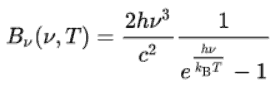
The Stefan–Boltzmann law determines the total blackbody emissive power, Eb, which is the sum of the radiation emitted over all wavelengths. Planck’s law describes the spectrum of blackbody radiation, which depends only on the object’s temperature and relates the spectral blackbody emissive power, Ebλ. This law is named after a German theoretical physicist Max Planck, who proposed it in 1900. Planck’s law is a pioneering result of modern physics and quantum theory. Planck’s hypothesis that energy is radiated and absorbed in discrete “quanta” (or energy packets) precisely matched the observed patterns of blackbody radiation and resolved the ultraviolet catastrophe.

Using this hypothesis, Planck showed that the spectral radiance of a body for frequency ν at absolute temperature T is given by:

plancks law - equationwhere

  • Bν(v,T) is the spectral radiance (the power per unit solid angle and per unit of area normal to the propagation) density of frequency ν radiation per unit frequency at thermal equilibrium at temperature T
  • h is the Planck constant
  • c is the speed of light in a vacuum
  • kB is the Boltzmann constant
  • ν is the frequency of the electromagnetic radiation
  • T is the absolute temperature of the body

The Planck’s law has the following important features:

  • The emitted radiation varies continuously with wavelength.
  • At any wavelength the magnitude of the emitted radiation increases with increasing temperature.
  • The spectral region in which the radiation is concentrated depends on temperature, with comparatively more radiation appearing at shorter wavelengths as the temperature increases (Wien’s Displacement Law).
 
Ultraviolet Catastrophe
Before the Planck’s hypothesis, physicists tried to describe spectral radiance of electromagnetic radiation by classical physics. The approximation based on classical physsics is known as the Rayleigh-Jeans law.

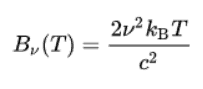
Similarly as for the Planck’s law, the Rayleigh-Jeans law gives the spectral radiance of a body as a function of frequency ν at absolute temperature T:

Rayleigh-Jeans Law - equationwhere

  • Bν(v,T) is the spectral radiance (the power per unit solid angle and per unit of area normal to the propagation) density of frequency ν radiation per unit frequency at thermal equilibrium at temperature T
  • c is the speed of light in a vacuum
  • kB is the Boltzmann constant
  • ν is the frequency of the electromagnetic radiation
  • T is the absolute temperature of the body

&nbsp;

ultraviolet catastrophe
The ultraviolet catastrophe is the error at short wavelengths in the Rayleigh–Jeans law (depicted as “classical theory” in the graph) for the energy emitted by an ideal black-body. The error, much more pronounced for short wavelengths, is the difference between the black curve (as classically predicted by the Rayleigh–Jeans law) and the blue curve (the measured curve as predicted by Planck’s law).
Source: wikipedia.org License: Public Domain

Electromagnetic spectrum predicted by this formula agrees with experimental results at low frequencies (large wavelengths) but strongly disagrees at high frequencies (short wavelengths). This inconsistency between observations and the predictions of classical physics is commonly known as the ultraviolet catastrophe or Rayleigh–Jeans catastrophe. By calculating the total amount of radiant energy (i.e., the sum of emissions in all frequency ranges), it can be shown that a blackbody in this case would release an infinite amount of energy, which is in contradiction with the law of conservation of energy.

The study of the laws of blackbodies and the failure of classical physics to describe them helped establish the foundations of quantum mechanics. Solution of this problem was proposed by a German theoretical physicist Max Planck, who introduced very strange assumption (for the time), that energy is radiated and absorbed in discrete “quanta” (or energy packets).

Blackbody Radiation

It is known that the amount of radiation energy emitted from a surface at a given wavelength depends on the material of the body and the condition of its surface as well as the surface temperature. Therefore, various materials emit different amounts of radiant energy even whhen they are at the same temperature. A body that emits the maximum amount of heat for its absolute temperature is called a blackbody.

blackbody radiationA blackbody is an idealized physical body, that has specific properties. By definition, a black body in thermal equilibrium has an emissivity of ε = 1.0. Real objects do not radiate as much heat as a perfect black body. They radiate less heat than a black body and therefore are called gray bodies.

The surface of a blackbody emits thermal radiation at the rate of approximately 448 watts per square metre at room temperature (25 °C, 298.15 K). Real objects with emissivities less than 1.0 (e.g. copper wire) emit radiation at correspondingly lower rates (e.g. 448 x 0.03 = 13.4 W/m2). Emissivity plays important role in heat transfer problems. For example, solar heat collectors incorporate selective surfaces that have very low emissivities. These collectors waste very little of the solar energy through emission of thermal radiation.

Since the absorptivity and the emissivity are interconnected by the Kirchhoff’s Law of thermal radiation, a blackbody is also a perfect absorber of electromagnetic radiation.

Kirchhoff’s Law of thermal radiation:

For an arbitrary body emitting and absorbing thermal radiation in thermodynamic equilibrium, the emissivity is equal to the absorptivity.

emissivity ε = absorptivity α

A blackbody absorbs all incident electromagnetic radiation, regardless of frequency or angle of incidence. Its absorptivity is therefore equal to unity, which is also the highest possible value. That is, a blackbody is a perfect absorber (and a perfect emitter).

Note that visible radiation occupies a very narrow band of the spectrum from 400 to 760 nm, we cannot make any judgments about the blackness of a surface on the basis of visual observations. For example, consider white paper that reflects visible light and thus appear white. On the other hand it is essentially black for infrared radiation (absorptivity α = 0.94) since they strongly absorb long-wavelength radiation.

 
References:
Heat Transfer:
  1. Fundamentals of Heat and Mass Transfer, 7th Edition. Theodore L. Bergman, Adrienne S. Lavine, Frank P. Incropera. John Wiley & Sons, Incorporated, 2011. ISBN: 9781118137253.
  2. Heat and Mass Transfer. Yunus A. Cengel. McGraw-Hill Education, 2011. ISBN: 9780071077866.
  3. U.S. Department of Energy, Thermodynamics, Heat Transfer and Fluid Flow. DOE Fundamentals Handbook, Volume 2 of 3. May 2016.

Nuclear and Reactor Physics:

  1. J. R. Lamarsh, Introduction to Nuclear Reactor Theory, 2nd ed., Addison-Wesley, Reading, MA (1983).
  2. J. R. Lamarsh, A. J. Baratta, Introduction to Nuclear Engineering, 3d ed., Prentice-Hall, 2001, ISBN: 0-201-82498-1.
  3. W. M. Stacey, Nuclear Reactor Physics, John Wiley & Sons, 2001, ISBN: 0- 471-39127-1.
  4. Glasstone, Sesonske. Nuclear Reactor Engineering: Reactor Systems Engineering, Springer; 4th edition, 1994, ISBN: 978-0412985317
  5. W.S.C. Williams. Nuclear and Particle Physics. Clarendon Press; 1 edition, 1991, ISBN: 978-0198520467
  6. G.R.Keepin. Physics of Nuclear Kinetics. Addison-Wesley Pub. Co; 1st edition, 1965
  7. Robert Reed Burn, Introduction to Nuclear Reactor Operation, 1988.
  8. U.S. Department of Energy, Nuclear Physics and Reactor Theory. DOE Fundamentals Handbook, Volume 1 and 2. January 1993.
  9. Paul Reuss, Neutron Physics. EDP Sciences, 2008. ISBN: 978-2759800414.

Advanced Reactor Physics:

  1. K. O. Ott, W. A. Bezella, Introductory Nuclear Reactor Statics, American Nuclear Society, Revised edition (1989), 1989, ISBN: 0-894-48033-2.
  2. K. O. Ott, R. J. Neuhold, Introductory Nuclear Reactor Dynamics, American Nuclear Society, 1985, ISBN: 0-894-48029-4.
  3. D. L. Hetrick, Dynamics of Nuclear Reactors, American Nuclear Society, 1993, ISBN: 0-894-48453-2.
  4. E. E. Lewis, W. F. Miller, Computational Methods of Neutron Transport, American Nuclear Society, 1993, ISBN: 0-894-48452-4.

See also:

Radiation

We hope, this article, Planck’s Law – Planck’s Hypothesis, helps you. If so, give us a like in the sidebar. Main purpose of this website is to help the public to learn some interesting and important information about thermal engineering.

What is Wien’s Displacement Law – Definition

Wien’s displacement law (named after a German physicist) describes the shift of that peak in terms of temperature, proportional to Wien’s displacement constant.

Wien’s Displacement Law

blackbody radiationAs can be seen from the figure, the blackbody radiation curve for different temperatures peaks at a wavelength inversely proportional to the temperature. Wien’s law (named after a German physicist) describes the shift of that peak in terms of temperature. Wien’s displacement law, and the fact that the frequency is inversely proportional to the wavelength, also indicates that the peak frequency fmax  (object’s color) is proportional to the absolute temperature T of the blackbody. Therefore, as temperature increases, the glow color changes from red to yellow to white to blue.

According to Wien’s displacement law, the spectral radiance of black body radiation per unit wavelength, peaks at the wavelength λmax given by:

Wien’s Displacement Law - equationwhere T is the absolute temperature in Kelvins, b is a constant of proportionality, known as Wien’s displacement constant, equal to 2.8978 × 10⁻³ K.m. It must be noted that even at a white-hot temperature of 2000 K, about 99% of the radiant energy is still radiated away in the infrared (invisible) spectrum.

Although the shift of that peak is a direct consequence of the Planck’s law, it had been discovered by Wilhelm Wien several years before Max Planck developed that more general equation.

Blackbody Radiation

It is known that the amount of radiation energy emitted from a surface at a given wavelength depends on the material of the body and the condition of its surface as well as the surface temperature. Therefore, various materials emit different amounts of radiant energy even whhen they are at the same temperature. A body that emits the maximum amount of heat for its absolute temperature is called a blackbody.

A blackbody is an idealized physical body, that has specific properties. By definition, a black body in thermal equilibrium has an emissivity of ε = 1.0. Real objects do not radiate as much heat as a perfect black body. They radiate less heat than a black body and therefore are called gray bodies.

The surface of a blackbody emits thermal radiation at the rate of approximately 448 watts per square metre at room temperature (25 °C, 298.15 K). Real objects with emissivities less than 1.0 (e.g. copper wire) emit radiation at correspondingly lower rates (e.g. 448 x 0.03 = 13.4 W/m2). Emissivity plays important role in heat transfer problems. For example, solar heat collectors incorporate selective surfaces that have very low emissivities. These collectors waste very little of the solar energy through emission of thermal radiation.

Since the absorptivity and the emissivity are interconnected by the Kirchhoff’s Law of thermal radiation, a blackbody is also a perfect absorber of electromagnetic radiation.

Kirchhoff’s Law of thermal radiation:

For an arbitrary body emitting and absorbing thermal radiation in thermodynamic equilibrium, the emissivity is equal to the absorptivity.

emissivity ε = absorptivity α

A blackbody absorbs all incident electromagnetic radiation, regardless of frequency or angle of incidence. Its absorptivity is therefore equal to unity, which is also the highest possible value. That is, a blackbody is a perfect absorber (and a perfect emitter).

Note that visible radiation occupies a very narrow band of the spectrum from 400 to 760 nm, we cannot make any judgments about the blackness of a surface on the basis of visual observations. For example, consider white paper that reflects visible light and thus appear white. On the other hand it is essentially black for infrared radiation (absorptivity α = 0.94) since they strongly absorb long-wavelength radiation.

 
References:
Heat Transfer:
  1. Fundamentals of Heat and Mass Transfer, 7th Edition. Theodore L. Bergman, Adrienne S. Lavine, Frank P. Incropera. John Wiley & Sons, Incorporated, 2011. ISBN: 9781118137253.
  2. Heat and Mass Transfer. Yunus A. Cengel. McGraw-Hill Education, 2011. ISBN: 9780071077866.
  3. U.S. Department of Energy, Thermodynamics, Heat Transfer and Fluid Flow. DOE Fundamentals Handbook, Volume 2 of 3. May 2016.

Nuclear and Reactor Physics:

  1. J. R. Lamarsh, Introduction to Nuclear Reactor Theory, 2nd ed., Addison-Wesley, Reading, MA (1983).
  2. J. R. Lamarsh, A. J. Baratta, Introduction to Nuclear Engineering, 3d ed., Prentice-Hall, 2001, ISBN: 0-201-82498-1.
  3. W. M. Stacey, Nuclear Reactor Physics, John Wiley & Sons, 2001, ISBN: 0- 471-39127-1.
  4. Glasstone, Sesonske. Nuclear Reactor Engineering: Reactor Systems Engineering, Springer; 4th edition, 1994, ISBN: 978-0412985317
  5. W.S.C. Williams. Nuclear and Particle Physics. Clarendon Press; 1 edition, 1991, ISBN: 978-0198520467
  6. G.R.Keepin. Physics of Nuclear Kinetics. Addison-Wesley Pub. Co; 1st edition, 1965
  7. Robert Reed Burn, Introduction to Nuclear Reactor Operation, 1988.
  8. U.S. Department of Energy, Nuclear Physics and Reactor Theory. DOE Fundamentals Handbook, Volume 1 and 2. January 1993.
  9. Paul Reuss, Neutron Physics. EDP Sciences, 2008. ISBN: 978-2759800414.

Advanced Reactor Physics:

  1. K. O. Ott, W. A. Bezella, Introductory Nuclear Reactor Statics, American Nuclear Society, Revised edition (1989), 1989, ISBN: 0-894-48033-2.
  2. K. O. Ott, R. J. Neuhold, Introductory Nuclear Reactor Dynamics, American Nuclear Society, 1985, ISBN: 0-894-48029-4.
  3. D. L. Hetrick, Dynamics of Nuclear Reactors, American Nuclear Society, 1993, ISBN: 0-894-48453-2.
  4. E. E. Lewis, W. F. Miller, Computational Methods of Neutron Transport, American Nuclear Society, 1993, ISBN: 0-894-48452-4.

See also:

Radiation

We hope, this article, Wien’s Displacement Law, helps you. If so, give us a like in the sidebar. Main purpose of this website is to help the public to learn some interesting and important information about thermal engineering.

What is Ultraviolet Catastrophe – Rayleigh-Jeans Catastrophe – Definition

The inconsistency between observations and the predictions of classical physics is known as the ultraviolet catastrophe or Rayleigh–Jeans catastrophe. Thermal Engineering

Ultraviolet Catastrophe

Before the Planck’s hypothesis, physicists tried to describe spectral radiance of electromagnetic radiation by classical physics. The approximation based on classical physsics is known as the Rayleigh-Jeans law.

Similarly as for the Planck’s law, the Rayleigh-Jeans law gives the spectral radiance of a body as a function of frequency ν at absolute temperature T:

Rayleigh-Jeans Law - equationwhere

  • Bν(v,T) is the spectral radiance (the power per unit solid angle and per unit of area normal to the propagation) density of frequency ν radiation per unit frequency at thermal equilibrium at temperature T
  • c is the speed of light in a vacuum
  • kB is the Boltzmann constant
  • ν is the frequency of the electromagnetic radiation
  • T is the absolute temperature of the body
ultraviolet catastrophe
The ultraviolet catastrophe is the error at short wavelengths in the Rayleigh–Jeans law (depicted as “classical theory” in the graph) for the energy emitted by an ideal black-body. The error, much more pronounced for short wavelengths, is the difference between the black curve (as classically predicted by the Rayleigh–Jeans law) and the blue curve (the measured curve as predicted by Planck’s law).
Source: wikipedia.org License: Public Domain

Electromagnetic spectrum predicted by this formula agrees with experimental results at low frequencies (large wavelengths) but strongly disagrees at high frequencies (short wavelengths). This inconsistency between observations and the predictions of classical physics is commonly known as the ultraviolet catastrophe or Rayleigh–Jeans catastrophe. By calculating the total amount of radiant energy (i.e., the sum of emissions in all frequency ranges), it can be shown that a blackbody in this case would release an infinite amount of energy, which is in contradiction with the law of conservation of energy.

The study of the laws of blackbodies and the failure of classical physics to describe them helped establish the foundations of quantum mechanics. Solution of this problem was proposed by a German theoretical physicist Max Planck, who introduced very strange assumption (for the time), that energy is radiated and absorbed in discrete “quanta” (or energy packets). Planck’s assumptions led to the correct form of the spectral distribution functions:

plancks law - equationwhere

  • Bν(v,T) is the spectral radiance (the power per unit solid angle and per unit of area normal to the propagation) density of frequency ν radiation per unit frequency at thermal equilibrium at temperature T
  • h is the Planck constant
  • c is the speed of light in a vacuum
  • kB is the Boltzmann constant
  • ν is the frequency of the electromagnetic radiation
  • T is the absolute temperature of the body

Albert Einstein solved the problem by postulating that Planck’s quanta were real physical particles, what we now call photons, not just a mathematical fiction.

Blackbody Radiation

It is known that the amount of radiation energy emitted from a surface at a given wavelength depends on the material of the body and the condition of its surface as well as the surface temperature. Therefore, various materials emit different amounts of radiant energy even whhen they are at the same temperature. A body that emits the maximum amount of heat for its absolute temperature is called a blackbody.

blackbody radiationA blackbody is an idealized physical body, that has specific properties. By definition, a black body in thermal equilibrium has an emissivity of ε = 1.0. Real objects do not radiate as much heat as a perfect black body. They radiate less heat than a black body and therefore are called gray bodies.

The surface of a blackbody emits thermal radiation at the rate of approximately 448 watts per square metre at room temperature (25 °C, 298.15 K). Real objects with emissivities less than 1.0 (e.g. copper wire) emit radiation at correspondingly lower rates (e.g. 448 x 0.03 = 13.4 W/m2). Emissivity plays important role in heat transfer problems. For example, solar heat collectors incorporate selective surfaces that have very low emissivities. These collectors waste very little of the solar energy through emission of thermal radiation.

Since the absorptivity and the emissivity are interconnected by the Kirchhoff’s Law of thermal radiation, a blackbody is also a perfect absorber of electromagnetic radiation.

Kirchhoff’s Law of thermal radiation:

For an arbitrary body emitting and absorbing thermal radiation in thermodynamic equilibrium, the emissivity is equal to the absorptivity.

emissivity ε = absorptivity α

A blackbody absorbs all incident electromagnetic radiation, regardless of frequency or angle of incidence. Its absorptivity is therefore equal to unity, which is also the highest possible value. That is, a blackbody is a perfect absorber (and a perfect emitter).

Note that visible radiation occupies a very narrow band of the spectrum from 400 to 760 nm, we cannot make any judgments about the blackness of a surface on the basis of visual observations. For example, consider white paper that reflects visible light and thus appear white. On the other hand it is essentially black for infrared radiation (absorptivity α = 0.94) since they strongly absorb long-wavelength radiation.

 
References:
Heat Transfer:
  1. Fundamentals of Heat and Mass Transfer, 7th Edition. Theodore L. Bergman, Adrienne S. Lavine, Frank P. Incropera. John Wiley & Sons, Incorporated, 2011. ISBN: 9781118137253.
  2. Heat and Mass Transfer. Yunus A. Cengel. McGraw-Hill Education, 2011. ISBN: 9780071077866.
  3. U.S. Department of Energy, Thermodynamics, Heat Transfer and Fluid Flow. DOE Fundamentals Handbook, Volume 2 of 3. May 2016.

Nuclear and Reactor Physics:

  1. J. R. Lamarsh, Introduction to Nuclear Reactor Theory, 2nd ed., Addison-Wesley, Reading, MA (1983).
  2. J. R. Lamarsh, A. J. Baratta, Introduction to Nuclear Engineering, 3d ed., Prentice-Hall, 2001, ISBN: 0-201-82498-1.
  3. W. M. Stacey, Nuclear Reactor Physics, John Wiley & Sons, 2001, ISBN: 0- 471-39127-1.
  4. Glasstone, Sesonske. Nuclear Reactor Engineering: Reactor Systems Engineering, Springer; 4th edition, 1994, ISBN: 978-0412985317
  5. W.S.C. Williams. Nuclear and Particle Physics. Clarendon Press; 1 edition, 1991, ISBN: 978-0198520467
  6. G.R.Keepin. Physics of Nuclear Kinetics. Addison-Wesley Pub. Co; 1st edition, 1965
  7. Robert Reed Burn, Introduction to Nuclear Reactor Operation, 1988.
  8. U.S. Department of Energy, Nuclear Physics and Reactor Theory. DOE Fundamentals Handbook, Volume 1 and 2. January 1993.
  9. Paul Reuss, Neutron Physics. EDP Sciences, 2008. ISBN: 978-2759800414.

Advanced Reactor Physics:

  1. K. O. Ott, W. A. Bezella, Introductory Nuclear Reactor Statics, American Nuclear Society, Revised edition (1989), 1989, ISBN: 0-894-48033-2.
  2. K. O. Ott, R. J. Neuhold, Introductory Nuclear Reactor Dynamics, American Nuclear Society, 1985, ISBN: 0-894-48029-4.
  3. D. L. Hetrick, Dynamics of Nuclear Reactors, American Nuclear Society, 1993, ISBN: 0-894-48453-2.
  4. E. E. Lewis, W. F. Miller, Computational Methods of Neutron Transport, American Nuclear Society, 1993, ISBN: 0-894-48452-4.

See also:

Radiation

We hope, this article, Ultraviolet Catastrophe – Rayleigh-Jeans Catastrophe, helps you. If so, give us a like in the sidebar. Main purpose of this website is to help the public to learn some interesting and important information about thermal engineering.
What is Advection – Heat Transport – Definition

Advection is the transport of a substance by bulk motion. Advection is sometimes confused with the more encompassing process of convection. Thermal Engineering

Advection

In engineering, the term convective heat transfer is used to describe the combined effects of conduction and fluid flow.  At this point, we have to add a new mechanism, which is known as advection (the transport of a substance by bulk motion). The properties that are carried with the advected substance are conserved properties such as energy, which is a commonly advected quantity. Advection is sometimes confused with the more encompassing process of convection, but convection includes energy transfer by both the bulk fluid motion (advection) and the random motion of fluid molecules (conduction or diffusion).

From the thermodynamic point of view, heat flows into a fluid by diffusion to increase its energy, the fluid then transfers (advects) this increased internal energy (not heat) from one location to another, and this is then followed by a second thermal interaction which transfers heat to a second body or system, again by diffusion. Advection requires currents in the fluid (as in a river or pipeline), and so cannot happen in rigid solids. It does not include transport of substances by molecular diffusion.

Advection Equation

The advection equation for a conserved quantity described by a scalar field ρ is expressed mathematically by a continuity equation:

∂⍴⁄∂t + ∇ . (⍴ ͞v) = σ

where

  • ∇ . is divergence,
  • ρ is the density of quantity q,
  • ⍴ ͞v is the flux of quantity q,
  • σ is the generation of q per unit volume per unit time. Terms that generate (σ > 0) or remove (σ < 0) q are referred to as a “sources” and “sinks” respectively. If q is a conserved quantity (such as energy), σ is equal to 0.
 
References:
Heat Transfer:
  1. Fundamentals of Heat and Mass Transfer, 7th Edition. Theodore L. Bergman, Adrienne S. Lavine, Frank P. Incropera. John Wiley & Sons, Incorporated, 2011. ISBN: 9781118137253.
  2. Heat and Mass Transfer. Yunus A. Cengel. McGraw-Hill Education, 2011. ISBN: 9780071077866.
  3. U.S. Department of Energy, Thermodynamics, Heat Transfer and Fluid Flow. DOE Fundamentals Handbook, Volume 2 of 3. May 2016.

Nuclear and Reactor Physics:

  1. J. R. Lamarsh, Introduction to Nuclear Reactor Theory, 2nd ed., Addison-Wesley, Reading, MA (1983).
  2. J. R. Lamarsh, A. J. Baratta, Introduction to Nuclear Engineering, 3d ed., Prentice-Hall, 2001, ISBN: 0-201-82498-1.
  3. W. M. Stacey, Nuclear Reactor Physics, John Wiley & Sons, 2001, ISBN: 0- 471-39127-1.
  4. Glasstone, Sesonske. Nuclear Reactor Engineering: Reactor Systems Engineering, Springer; 4th edition, 1994, ISBN: 978-0412985317
  5. W.S.C. Williams. Nuclear and Particle Physics. Clarendon Press; 1 edition, 1991, ISBN: 978-0198520467
  6. G.R.Keepin. Physics of Nuclear Kinetics. Addison-Wesley Pub. Co; 1st edition, 1965
  7. Robert Reed Burn, Introduction to Nuclear Reactor Operation, 1988.
  8. U.S. Department of Energy, Nuclear Physics and Reactor Theory. DOE Fundamentals Handbook, Volume 1 and 2. January 1993.
  9. Paul Reuss, Neutron Physics. EDP Sciences, 2008. ISBN: 978-2759800414.

Advanced Reactor Physics:

  1. K. O. Ott, W. A. Bezella, Introductory Nuclear Reactor Statics, American Nuclear Society, Revised edition (1989), 1989, ISBN: 0-894-48033-2.
  2. K. O. Ott, R. J. Neuhold, Introductory Nuclear Reactor Dynamics, American Nuclear Society, 1985, ISBN: 0-894-48029-4.
  3. D. L. Hetrick, Dynamics of Nuclear Reactors, American Nuclear Society, 1993, ISBN: 0-894-48453-2.
  4. E. E. Lewis, W. F. Miller, Computational Methods of Neutron Transport, American Nuclear Society, 1993, ISBN: 0-894-48452-4.

See also:

Heat Transfer

We hope, this article, Advection – Heat Transport, helps you. If so, give us a like in the sidebar. Main purpose of this website is to help the public to learn some interesting and important information about thermal engineering.
What is Heat Exchanger – Definition

Heat exchangers are devices that are used to transfer thermal energy from one fluid to another without mixing the two fluids. What is Heat Exchanger

Heat Exchangers

Surface Condenser Source: wikipedia.org License: CC BY-SA 3.0
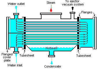
Surface Condenser

Heat exchangers are devices that are used to transfer thermal energy from one fluid to another without mixing the two fluids. The fluids are usually separated by a solid wall (with high thermal conductivity) to prevent mixing or they may be in direct contact.

The classic example of a heat exchanger is found in an internal combustion engine in which an engine coolant flows through radiator coils and air flows past the coils, which cools the coolant and heats the incoming air. In power engineering, common applications of heat exchangers include steam generators, fan coolers, cooling water heat exchangers, and condensers. For example, steam generator is used to convert feedwater into steam from heat produced in a nuclear reactor core. The steam produced drives the turbine.

Heat transfer in a heat exchanger usually involves convection in each fluid and thermal conduction through the wall separating the two fluids. In the analysis of heat exchangers,  it is often convenient to work with an overall heat transfer coefficient, known as a U-factor. The U-factor is defined by an expression analogous to Newton’s law of cooling.

Moreover, engineers also use the logarithmic mean temperature difference (LMTD) to determine the temperature driving force for heat transfer in heat exchangers.

Special Reference: John R. Thome, Engineering Data Book III. Wolverine Tube Inc. 2004.

Types of Heat Exchangers – Classification of Heat Exchangers

Heat exchangers are typically classified according to flow arrangement and type of construction. The simplest heat exchanger is one for which the hot and cold fluids move in the same or opposite directions. This heat exchanger consists of two concentric pipes of different diameters.

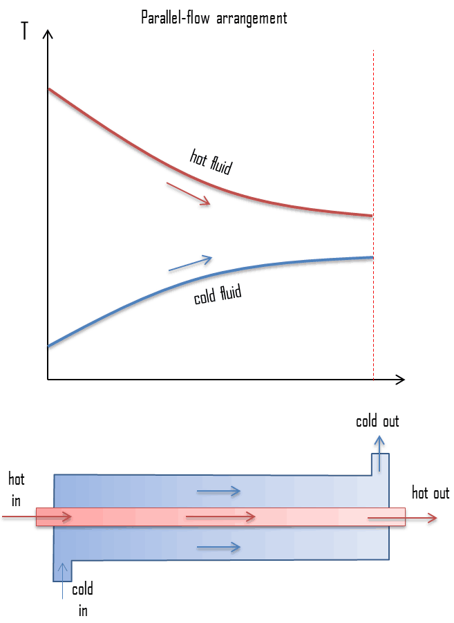
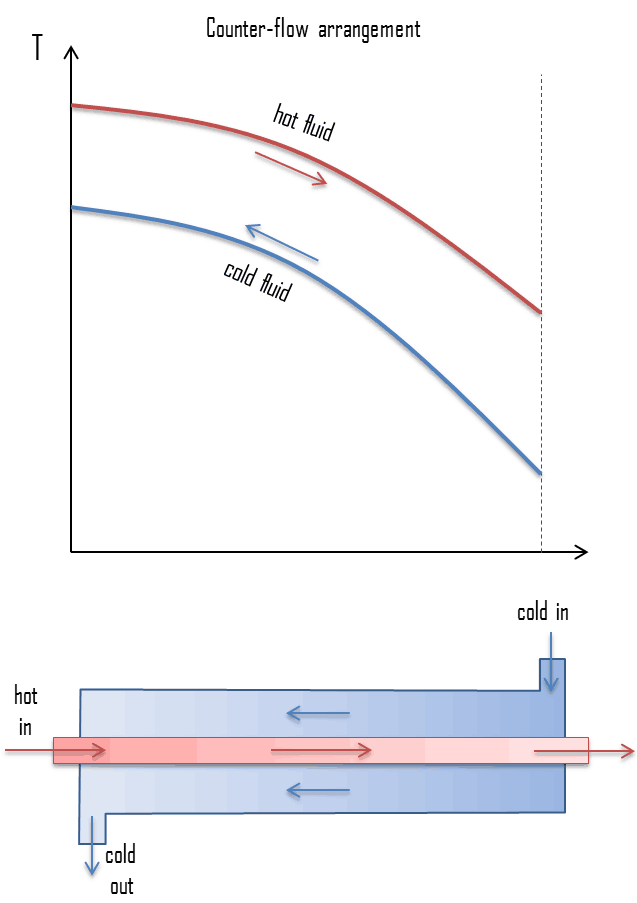
  • parallel-flow arrangement. In the parallel-flow arrangement, the hot and cold fluids enter at the same end, flow in the same direction, and leave at the same end.
  • counter-flow arrangement. In the counter-flow arrangement, the fluids enter at opposite ends, flow in opposite directions, and leave at opposite ends.

Figure represents the directions of fluid flow in the parallel and counter-flow exchangers. Under comparable conditions, more heat is transferred in a counter-flow arrangement than in a parallel flow heat exchanger. The temperature profiles of the two heat exchangers indicate two major disadvantages in the parallel-flow design.

  • The large temperature difference at the ends causes large thermal stresses.
  • The temperature of the cold fluid exiting the heat exchanger never exceeds the lowest temperature of the hot fluid.

The design of a parallel flow heat exchanger is advantageous when two fluids are required to be brought to nearly the same temperature.

heat exchanger - parallel-flow

heat exchanger - counter-flow

The heat transfer surface in heat exchangers can be arranged in several forms. Heat exchangers are therefore also classified as:
  • Double pipe heat exchangers. Double pipe heat exchangers are cheap for both design and maintenance, making them a good choice for small industries. In these exchangers one fluid flows inside the tube and the other fluid flows on the outside. Although they are simple and cheap, their low efficiency coupled with the high space occupied in large scales, has led modern industries to use more efficient heat exchangers like shell and tube.
  • Shell and tube heat exchangers. Shell and tube heat exchangers in their various construction modifications are probably the most widespread and commonly used basic heat exchanger configuration in industry. Shell-and-tube heat exchangers are further classified according to the number of shell and tube passes involved. Shell and tube heat exchangers are typically used for high-pressure applications (with pressures greater than 30 bar and temperatures greater than 260 °C). This is because the shell and tube heat exchangers can withstand high pressures due to their shape. In this type of heat exchanger, a number of small bore pipes are fitted between two tube plates and primary fluid flows through these tubes. The tube bundle is placed inside a shell and the secondary fluid flows through the shell and over the surface of the tubes. In nuclear engineering, this design of heat exchangers is widely used as in case of steam generator, which are used to convert feedwater into steam from heat produced in a nuclear reactor core. To increase the amount of heat transferred and the power generated, the heat exchange surface must be maximized. This is obtained by using tubes. Each steam generator can contain anywhere from 3,000 to 16,000 tubes, each about  19mm diameter.
  • Plate heat exchangers. A plate heat exchanger is a type of heat exchanger that uses metal plates to transfer heat between two fluids. This arrangement is popular with heat exchangers using air or gas as well as lower velocity fluid flow. The classic example of a heat exchanger is found in an internal combustion engine in which an engine coolant flows through radiator coils and air flows past the coils, which cools the coolant and heats the incoming air. When compared to shell and tube exchangers, the stacked-plate arrangement typically has lower volume and cost. Another difference between the two is that plate exchangers typically serve low to medium pressure fluids, compared to medium and high pressures of shell and tube.

Heat Exchanger Analysis – Heat Exchanger Calculation

Heat exchangers are commonly used in industry, and proper design of a heat exchanger depends on many variables. Following terms and methods are widely used to select an appropriate heat exchanger.

Overall Heat Transfer Coefficient

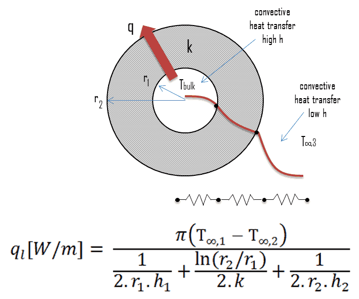
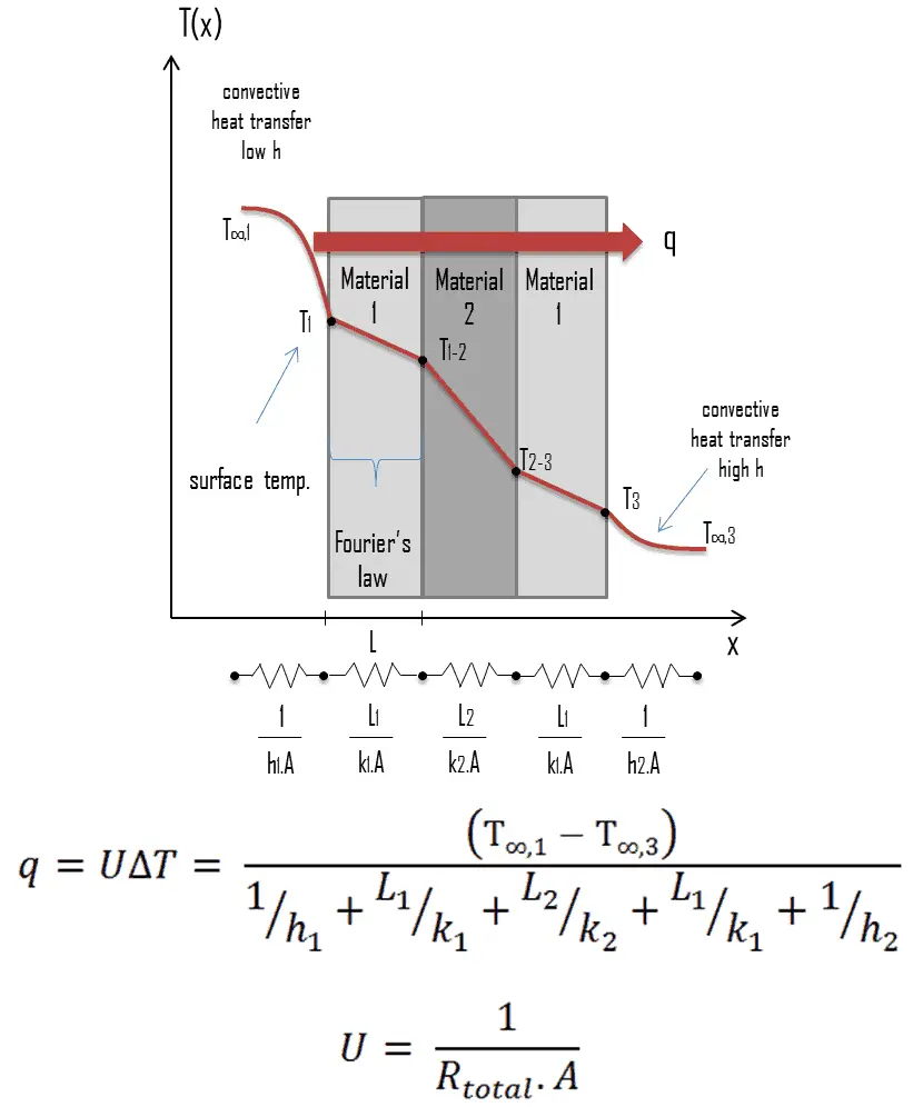
U-factor - Overall Heat Transfer CoefficientA heat exchanger typically involves two flowing fluids separated by a solid wall. Many of the heat transfer processes encountered in industry involve composite systems and even involve a combination of both conduction and convection. Heat is first transferred from the hot fluid to the wall by convection, through the wall by conduction, and from the wall to the cold fluid again by convection.

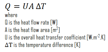
With these composite systems, it is often convenient to work with an overall heat transfer coefficient, known as a U-factor. The U-factor is defined by an expression analogous to Newton’s law of cooling:

overall heat transfer coefficient - equation

overall heat transfer coefficient - tableThe overall heat transfer coefficient, U, is related to the total thermal resistance and depends on the geometry of the problem. For example, heat transfer in a steam generator involves convection from the bulk of the reactor coolant to the steam generator inner tube surface, conduction through the tube wall, and convection (boiling) from the outer tube surface to the secondary side fluid.

In cases of combined heat transfer for a heat exchanger, there are two values for h. There is the convective heat transfer coefficient (h) for the fluid film inside the tubes and a convective heat transfer coefficient for the fluid film outside the tubes. The thermal conductivity (k) and thickness (Δx) of the tube wall must also be accounted for.

 
Overall Heat Transfer Coefficient – Plane Wall
U-factor - Overall Heat Transfer Coefficient
Overall Heat Transfer Coefficient – Cylindrical Tubes
Steady heat transfer through multilayered cylindrical or spherical shells can be handled just like multilayered plane walls.

Overall Heat Transfer Coefficient - Cylindrical Tubes

Online monitoring of commercial heat exchangers is done by tracking the overall heat transfer coefficient, because the overall heat transfer coefficient tends to decline over time due to fouling. By periodically calculating the overall heat transfer coefficient from exchanger flow rates and temperatures, the operator of the heat exchanger can estimate the lifetime of heat exchangers.
 
Fouling - Fouling Factor
Online monitoring of commercial heat exchangers is done by tracking the overall heat transfer coefficient, because the overall heat transfer coefficient tends to decline over time due to fouling. Fouling is the accumulation of unwanted material on solid surfaces to the detriment of function. The fouling materials can consist of either living organisms or a non-living substance (minerals or organic compounds). The layer of deposits represents additional resistance to heat transfer and causes the rate of heat transfer in a heat exchanger to decrease. As a result, fouling in heat exchangers reduces thermal efficiency, decreases heat flux, increases temperature on the hot side, decreases temperature on the cold side, induces under-deposit corrosion, increases use of cooling water. The net effect of these accumulations on heat transfer is represented by a fouling factor, Rf , which is a measure of the overall thermal resistance introduced by fouling.

Logarithmic Mean Temperature Difference – LMTD

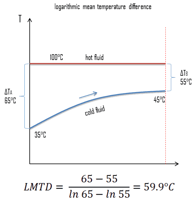
In order to solve certain heat exchanger problems, engineers often use a log mean temperature difference (LMTD), which is used to determine the temperature driving force for heat transfer in heat exchangers. LMTD is introduced due to the fact, the temperature change that takes place across the heat exchanger from the entrance to the exit is not linear.

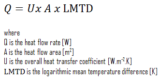
The heat transfer through the wall of heat exchanger at a given location is given by the following equation:

overall heat transfer coefficient - equation

logarithmic mean temperature difference - exampleHere the value of overall heat transfer coefficient can be assumed as a constant. On the other hand the temperature difference continuously varies with location (especially in counter-flow arrangement). In order to determine the total heat flow, either the heat flow should be summed up using elemental areas and the temperature difference at the location or more conveniently engineers can average the value of temperature difference. The heat exchanger equation can be solved much easier if we could define a “Mean Temperature Difference” (MTD). It can be seen from the figure that the temperature difference varies along the flow and the arithmetic average may not be the real average, therefore engineers use the logarithmic mean temperature difference. The “Logarithmic Mean Temperature Difference“ (LMTD) is a logarithmic average of the temperature difference between the hot and cold feeds at each end of the heat exchanger. The larger the LMTD, the more heat is transferred. It can be seen from the figure that the temperature difference varies along the flow and the arithmetic average may not be the real average.

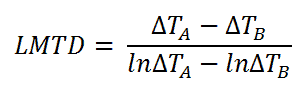
For heat exchanger that has two ends (which we call “A” and “B”) at which the hot and cold streams enter or exit on either side, the LMTD is defined as:

logarithmic mean temperature difference - definition

The heat transfer is then given by:

LMTD - heat transfer equation

This holds both for parallel-flow arrangement, where the streams enter from the same end, and for counter-flow arrangement, where they enter from different ends.

In a cross-flow, in which one system, usually the heat sink, has the same nominal temperature at all points on the heat transfer surface, a similar relation between exchanged heat and LMTD holds, but with a correction factor. A correction factor is also required for other more complex geometries, such as a shell and tube exchanger with baffles.

LMTD – Condensers and Boilers

Steam generator - counterflow heat exchanger
Temperature gradients in typical PWR steam generator.

Steam generators and condensers are also examples of components found in nuclear facilities where the concept of LMTD is needed to address certain problems. When the subcooled water enters the steam generator, it must be heated up to its boiling point and then it must be evaporated. Because evaporation is taking place at constant temperature, it cannot be used a single LMTD. In this case the heat exchanger has to be treated as a combination of two or three (when superheat occurs) heat exchangers.

Pinch Point – Heat Exchanger

There is another interesting aspect to the design in that the temperature difference known as ‘pinch’ can limit the performance of heat exchangers if the areas and flow rates are not properly designed. Pinch point is the location in heat exchanger where the temperature difference between hot and cold fluid is minimum at that location.

NTU Effectiveness Method

The log mean temperature difference (LMTD) method discussed in previous section is easy to use in heat exchanger analysis when the inlet and the outlet temperatures of the hot and cold fluids are known or can be determined from an energy balance. Therefore, the LMTD method is very suitable for determining the size and performance of a heat exchanger.

When direct knowledge of the LMTD is not available and the NTU method (Number of Transfer Units method) can be used. This method is based on a dimensionless parameter called the heat transfer effectiveness, defined as:

NTU Effectiveness Method - equation

As can be seen, the effectiveness is the ratio between the actual heat transfer rate and the maximum possible heat transfer rate. To define the effectiveness of a heat exchanger, we must first determine the maximum possible heat transfer rate, qmax, for the heat exchanger.

Further reading:

  1. Fundamentals of Heat and Mass Transfer, 7th Edition. Theodore L. Bergman, Adrienne S. Lavine, Frank P. Incropera. John Wiley & Sons, Incorporated, 2011. ISBN: 9781118137253.
  2. Heat and Mass Transfer. Yunus A. Cengel. McGraw-Hill Education, 2011. ISBN: 9780071077866.

Example: Calculation of Heat Exchanger

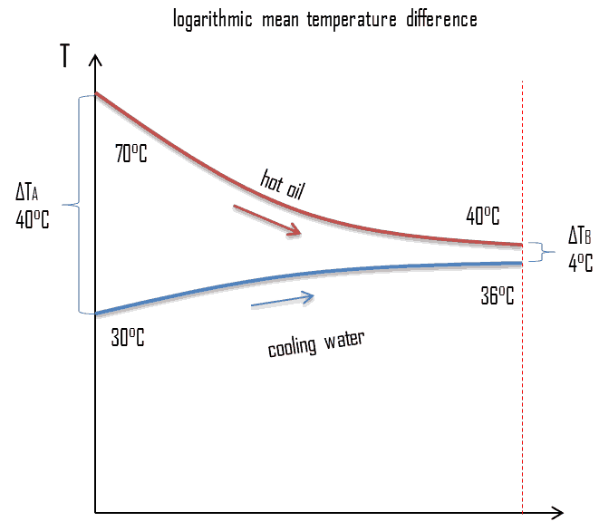
example - heat exchanger calculation - LMTDConsider a parallel-flow heat exchanger, which is used to cool oil from 70°C to 40°C using water available at 30°C. The outlet temperature of the water is 36°C.  The rate of flow of oil is 1 kg/s. The specific heat of the oil is 2.2 kJ/kg K. The overall heat transfer coefficient U = 200 W/m2 K.

Calculate the logarithmic mean temperature difference. Determine the area of this heat exchanger required for this performance.

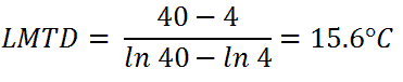
  1. LMTD

The logarithmic mean temperature difference can be calculated simply using its definition:

LMTD - example

  1. Area of Heat Exchanger

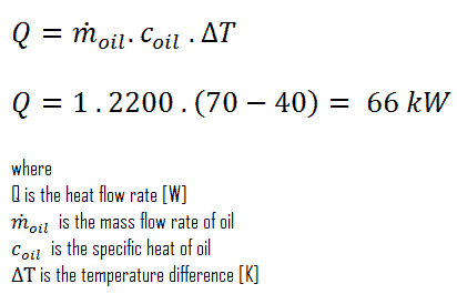
To calculated the area of this heat exchanger, we have to calculate the heat flow rate using mass flow rate of oil and LMTD.

Energy Balance - Example

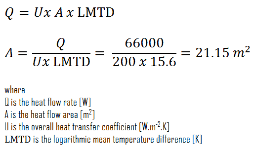
The required area of this heat exchanger can be then directly calculated using general heat transfer equation:

heat exchanger - calculation

Recuperator and Regenerative Heat Exchanger

In general, the heat exchangers used in regeneration may be classified as either regenerators or recuperators.

  • Regenerator is a type of heat exchanger where heat from the hot fluid is intermittently stored in a thermal storage medium before it is transferred to the cold fluid. It has a single flow path in which the hot and cold fluids alternately pass through.
  • Recuperator is a type of heat exchanger has separate flow paths for each fluid along their own passages and heat is transferred through the separating walls. Recuperators (e.g. economisers) are often used in power engineering, to increase the overall efficiency of thermodynamic cycles. For example, in a gas turbine engine. The recuperator transfers some of the waste heat in the exhaust to the compressed air, thus preheating it before entering the combustion chamber. Many recuperators are designed as counter-flow heat exchangers.

Heat Regeneration

In steam turbines theory,  significant increases in the thermal efficiency of steam turbine can be achieved through reducing the amount of fuel that must be added in the boiler. This can be done by transferring heat (e.g. partially expanded steam) from certain sections of the steam turbine, which is normally well above the ambient temperature, to the feedwater. This process is known as heat regeneration and a variety of heat regenerators can be used for this purpose. Sometimes engineers use the term economiser that are heat exchangers intended to reduce energy consumption, especially in case of preheating of a fluid.

As can be seen in the article “Steam Generator”, the feedwater (secondary circuit) at the inlet of the steam generator may have about ~230°C (446°F)and then is heated to the boiling point of that fluid (280°C; 536°F; 6,5MPa)and evaporated. But the condensate at the condenser outlet may have about 40°C, so the heat regeneration in typical PWR is significant and very important:

  • Heat regeneration increases the thermal efficiency, since more of the heat flow into the cycle occurs at higher temperature.
  • Heat regeneration causes a decrease in the mass flow rate through low-pressure stage of the steam turbine, thus increases LP Isentropic Turbine Efficiency. Note that at the last stage of expansion the steam has very high specific volume.
  • Heat regeneration causes an increases in working steam quality, since the drains are situated at the periphery of turbine casing, where is higher concentration of water droplets.
 
References:
Heat Transfer:
  1. Fundamentals of Heat and Mass Transfer, 7th Edition. Theodore L. Bergman, Adrienne S. Lavine, Frank P. Incropera. John Wiley & Sons, Incorporated, 2011. ISBN: 9781118137253.
  2. Heat and Mass Transfer. Yunus A. Cengel. McGraw-Hill Education, 2011. ISBN: 9780071077866.
  3. U.S. Department of Energy, Thermodynamics, Heat Transfer and Fluid Flow. DOE Fundamentals Handbook, Volume 2 of 3. May 2016.

Nuclear and Reactor Physics:

  1. J. R. Lamarsh, Introduction to Nuclear Reactor Theory, 2nd ed., Addison-Wesley, Reading, MA (1983).
  2. J. R. Lamarsh, A. J. Baratta, Introduction to Nuclear Engineering, 3d ed., Prentice-Hall, 2001, ISBN: 0-201-82498-1.
  3. W. M. Stacey, Nuclear Reactor Physics, John Wiley & Sons, 2001, ISBN: 0- 471-39127-1.
  4. Glasstone, Sesonske. Nuclear Reactor Engineering: Reactor Systems Engineering, Springer; 4th edition, 1994, ISBN: 978-0412985317
  5. W.S.C. Williams. Nuclear and Particle Physics. Clarendon Press; 1 edition, 1991, ISBN: 978-0198520467
  6. G.R.Keepin. Physics of Nuclear Kinetics. Addison-Wesley Pub. Co; 1st edition, 1965
  7. Robert Reed Burn, Introduction to Nuclear Reactor Operation, 1988.
  8. U.S. Department of Energy, Nuclear Physics and Reactor Theory. DOE Fundamentals Handbook, Volume 1 and 2. January 1993.
  9. Paul Reuss, Neutron Physics. EDP Sciences, 2008. ISBN: 978-2759800414.

Advanced Reactor Physics:

  1. K. O. Ott, W. A. Bezella, Introductory Nuclear Reactor Statics, American Nuclear Society, Revised edition (1989), 1989, ISBN: 0-894-48033-2.
  2. K. O. Ott, R. J. Neuhold, Introductory Nuclear Reactor Dynamics, American Nuclear Society, 1985, ISBN: 0-894-48029-4.
  3. D. L. Hetrick, Dynamics of Nuclear Reactors, American Nuclear Society, 1993, ISBN: 0-894-48453-2.
  4. E. E. Lewis, W. F. Miller, Computational Methods of Neutron Transport, American Nuclear Society, 1993, ISBN: 0-894-48452-4.

See also:

Heat Transfer

We hope, this article, Heat Exchanger, helps you. If so, give us a like in the sidebar. Main purpose of this website is to help the public to learn some interesting and important information about thermal engineering.
What is Type of Heat Exchangers – Classification of Heat Exchangers – Definition

Types of Heat Exchangers – Classification. Heat exchangers are typically classified according to flow arrangement and type of construction. Thermal Engineering

Heat Exchangers

Surface Condenser Source: wikipedia.org License: CC BY-SA 3.0
Surface Condenser

Heat exchangers are devices that are used to transfer thermal energy from one fluid to another without mixing the two fluids. The fluids are usually separated by a solid wall (with high thermal conductivity) to prevent mixing or they may be in direct contact.

The classic example of a heat exchanger is found in an internal combustion engine in which an engine coolant flows through radiator coils and air flows past the coils, which cools the coolant and heats the incoming air. In power engineering, common applications of heat exchangers include steam generators, fan coolers, cooling water heat exchangers, and condensers. For example, steam generator is used to convert feedwater into steam from heat produced in a nuclear reactor core. The steam produced drives the turbine.

Heat transfer in a heat exchanger usually involves convection in each fluid and thermal conduction through the wall separating the two fluids. In the analysis of heat exchangers,  it is often convenient to work with an overall heat transfer coefficient, known as a U-factor. The U-factor is defined by an expression analogous to Newton’s law of cooling.

Moreover, engineers also use the logarithmic mean temperature difference (LMTD) to determine the temperature driving force for heat transfer in heat exchangers.

Special Reference: John R. Thome, Engineering Data Book III. Wolverine Tube Inc. 2004.

Types of Heat Exchangers – Classification of Heat Exchangers

Heat exchangers are typically classified according to flow arrangement and type of construction. The simplest heat exchanger is one for which the hot and cold fluids move in the same or opposite directions. This heat exchanger consists of two concentric pipes of different diameters.

  • parallel-flow arrangement. In the parallel-flow arrangement, the hot and cold fluids enter at the same end, flow in the same direction, and leave at the same end.
  • counter-flow arrangement. In the counter-flow arrangement, the fluids enter at opposite ends, flow in opposite directions, and leave at opposite ends.

Figure represents the directions of fluid flow in the parallel and counter-flow exchangers. Under comparable conditions, more heat is transferred in a counter-flow arrangement than in a parallel flow heat exchanger. The temperature profiles of the two heat exchangers indicate two major disadvantages in the parallel-flow design.

  • The large temperature difference at the ends causes large thermal stresses.
  • The temperature of the cold fluid exiting the heat exchanger never exceeds the lowest temperature of the hot fluid.

The design of a parallel flow heat exchanger is advantageous when two fluids are required to be brought to nearly the same temperature.

heat exchanger - parallel-flow

heat exchanger - counter-flow

The heat transfer surface in heat exchangers can be arranged in several forms. Heat exchangers are therefore also classified as:
  • Double pipe heat exchangers. Double pipe heat exchangers are cheap for both design and maintenance, making them a good choice for small industries. In these exchangers one fluid flows inside the tube and the other fluid flows on the outside. Although they are simple and cheap, their low efficiency coupled with the high space occupied in large scales, has led modern industries to use more efficient heat exchangers like shell and tube.
  • Shell and tube heat exchangers. Shell and tube heat exchangers in their various construction modifications are probably the most widespread and commonly used basic heat exchanger configuration in industry. Shell-and-tube heat exchangers are further classified according to the number of shell and tube passes involved. Shell and tube heat exchangers are typically used for high-pressure applications (with pressures greater than 30 bar and temperatures greater than 260 °C). This is because the shell and tube heat exchangers can withstand high pressures due to their shape. In this type of heat exchanger, a number of small bore pipes are fitted between two tube plates and primary fluid flows through these tubes. The tube bundle is placed inside a shell and the secondary fluid flows through the shell and over the surface of the tubes. In nuclear engineering, this design of heat exchangers is widely used as in case of steam generator, which are used to convert feedwater into steam from heat produced in a nuclear reactor core. To increase the amount of heat transferred and the power generated, the heat exchange surface must be maximized. This is obtained by using tubes. Each steam generator can contain anywhere from 3,000 to 16,000 tubes, each about  19mm diameter.
  • Plate heat exchangers. A plate heat exchanger is a type of heat exchanger that uses metal plates to transfer heat between two fluids. This arrangement is popular with heat exchangers using air or gas as well as lower velocity fluid flow. The classic example of a heat exchanger is found in an internal combustion engine in which an engine coolant flows through radiator coils and air flows past the coils, which cools the coolant and heats the incoming air. When compared to shell and tube exchangers, the stacked-plate arrangement typically has lower volume and cost. Another difference between the two is that plate exchangers typically serve low to medium pressure fluids, compared to medium and high pressures of shell and tube.
 
References:
Heat Transfer:
  1. Fundamentals of Heat and Mass Transfer, 7th Edition. Theodore L. Bergman, Adrienne S. Lavine, Frank P. Incropera. John Wiley & Sons, Incorporated, 2011. ISBN: 9781118137253.
  2. Heat and Mass Transfer. Yunus A. Cengel. McGraw-Hill Education, 2011. ISBN: 9780071077866.
  3. U.S. Department of Energy, Thermodynamics, Heat Transfer and Fluid Flow. DOE Fundamentals Handbook, Volume 2 of 3. May 2016.

Nuclear and Reactor Physics:

  1. J. R. Lamarsh, Introduction to Nuclear Reactor Theory, 2nd ed., Addison-Wesley, Reading, MA (1983).
  2. J. R. Lamarsh, A. J. Baratta, Introduction to Nuclear Engineering, 3d ed., Prentice-Hall, 2001, ISBN: 0-201-82498-1.
  3. W. M. Stacey, Nuclear Reactor Physics, John Wiley & Sons, 2001, ISBN: 0- 471-39127-1.
  4. Glasstone, Sesonske. Nuclear Reactor Engineering: Reactor Systems Engineering, Springer; 4th edition, 1994, ISBN: 978-0412985317
  5. W.S.C. Williams. Nuclear and Particle Physics. Clarendon Press; 1 edition, 1991, ISBN: 978-0198520467
  6. G.R.Keepin. Physics of Nuclear Kinetics. Addison-Wesley Pub. Co; 1st edition, 1965
  7. Robert Reed Burn, Introduction to Nuclear Reactor Operation, 1988.
  8. U.S. Department of Energy, Nuclear Physics and Reactor Theory. DOE Fundamentals Handbook, Volume 1 and 2. January 1993.
  9. Paul Reuss, Neutron Physics. EDP Sciences, 2008. ISBN: 978-2759800414.

Advanced Reactor Physics:

  1. K. O. Ott, W. A. Bezella, Introductory Nuclear Reactor Statics, American Nuclear Society, Revised edition (1989), 1989, ISBN: 0-894-48033-2.
  2. K. O. Ott, R. J. Neuhold, Introductory Nuclear Reactor Dynamics, American Nuclear Society, 1985, ISBN: 0-894-48029-4.
  3. D. L. Hetrick, Dynamics of Nuclear Reactors, American Nuclear Society, 1993, ISBN: 0-894-48453-2.
  4. E. E. Lewis, W. F. Miller, Computational Methods of Neutron Transport, American Nuclear Society, 1993, ISBN: 0-894-48452-4.

See also:

Heat Exchangers

We hope, this article, Type of Heat Exchangers – Classification of Heat Exchangers, helps you. If so, give us a like in the sidebar. Main purpose of this website is to help the public to learn some interesting and important information about thermal engineering.
What is Parallel-flow and Counter-flow Heat Exchanger – Definition

Parallel-flow and Counter-flow Heat Exchanger. Figure represents the directions of fluid flow in the parallel and counter-flow exchangers. Thermal Engineering

Parallel-flow and Counter-flow Heat Exchanger

Heat exchangers are typically classified according to flow arrangement and type of construction. The simplest heat exchanger is one for which the hot and cold fluids move in the same or opposite directions. This heat exchanger consists of two concentric pipes of different diameters.

  • parallel-flow arrangement. In the parallel-flow arrangement, the hot and cold fluids enter at the same end, flow in the same direction, and leave at the same end.
  • counter-flow arrangement. In the counter-flow arrangement, the fluids enter at opposite ends, flow in opposite directions, and leave at opposite ends.

Figure represents the directions of fluid flow in the parallel and counter-flow exchangers. Under comparable conditions, more heat is transferred in a counter-flow arrangement than in a parallel flow heat exchanger. The temperature profiles of the two heat exchangers indicate two major disadvantages in the parallel-flow design.

  • The large temperature difference at the ends causes large thermal stresses.
  • The temperature of the cold fluid exiting the heat exchanger never exceeds the lowest temperature of the hot fluid.

The design of a parallel flow heat exchanger is advantageous when two fluids are required to be brought to nearly the same temperature.

heat exchanger - parallel-flow

heat exchanger - counter-flow

 
References:
Heat Transfer:
  1. Fundamentals of Heat and Mass Transfer, 7th Edition. Theodore L. Bergman, Adrienne S. Lavine, Frank P. Incropera. John Wiley & Sons, Incorporated, 2011. ISBN: 9781118137253.
  2. Heat and Mass Transfer. Yunus A. Cengel. McGraw-Hill Education, 2011. ISBN: 9780071077866.
  3. U.S. Department of Energy, Thermodynamics, Heat Transfer and Fluid Flow. DOE Fundamentals Handbook, Volume 2 of 3. May 2016.

Nuclear and Reactor Physics:

  1. J. R. Lamarsh, Introduction to Nuclear Reactor Theory, 2nd ed., Addison-Wesley, Reading, MA (1983).
  2. J. R. Lamarsh, A. J. Baratta, Introduction to Nuclear Engineering, 3d ed., Prentice-Hall, 2001, ISBN: 0-201-82498-1.
  3. W. M. Stacey, Nuclear Reactor Physics, John Wiley & Sons, 2001, ISBN: 0- 471-39127-1.
  4. Glasstone, Sesonske. Nuclear Reactor Engineering: Reactor Systems Engineering, Springer; 4th edition, 1994, ISBN: 978-0412985317
  5. W.S.C. Williams. Nuclear and Particle Physics. Clarendon Press; 1 edition, 1991, ISBN: 978-0198520467
  6. G.R.Keepin. Physics of Nuclear Kinetics. Addison-Wesley Pub. Co; 1st edition, 1965
  7. Robert Reed Burn, Introduction to Nuclear Reactor Operation, 1988.
  8. U.S. Department of Energy, Nuclear Physics and Reactor Theory. DOE Fundamentals Handbook, Volume 1 and 2. January 1993.
  9. Paul Reuss, Neutron Physics. EDP Sciences, 2008. ISBN: 978-2759800414.

Advanced Reactor Physics:

  1. K. O. Ott, W. A. Bezella, Introductory Nuclear Reactor Statics, American Nuclear Society, Revised edition (1989), 1989, ISBN: 0-894-48033-2.
  2. K. O. Ott, R. J. Neuhold, Introductory Nuclear Reactor Dynamics, American Nuclear Society, 1985, ISBN: 0-894-48029-4.
  3. D. L. Hetrick, Dynamics of Nuclear Reactors, American Nuclear Society, 1993, ISBN: 0-894-48453-2.
  4. E. E. Lewis, W. F. Miller, Computational Methods of Neutron Transport, American Nuclear Society, 1993, ISBN: 0-894-48452-4.

See also:

Heat Exchangers

We hope, this article, Parallel-flow and Counter-flow Heat Exchanger, helps you. If so, give us a like in the sidebar. Main purpose of this website is to help the public to learn some interesting and important information about thermal engineering.
What is Double Pipe Heat Exchanger – Definition

Double pipe heat exchangers are cheap for both design and maintenance, making them a good choice for small industries. Double Pipe Heat Exchangers

Double Pipe Heat Exchangers

Double pipe heat exchangers

Double pipe heat exchangers are cheap for both design and maintenance, making them a good choice for small industries. In these exchangers one fluid flows inside the tube and the other fluid flows on the outside. Although they are simple and cheap, their low efficiency coupled with the high space occupied in large scales, has led modern industries to use more efficient heat exchangers like shell and tube.

Heat Exchanger – Flow Direction

Heat exchangers are typically classified according to flow arrangement and type of construction. The simplest heat exchanger is one for which the hot and cold fluids move in the same or opposite directions. This heat exchanger consists of two concentric pipes of different diameters.

  • parallel-flow arrangement. In the parallel-flow arrangement, the hot and cold fluids enter at the same end, flow in the same direction, and leave at the same end.
  • counter-flow arrangement. In the counter-flow arrangement, the fluids enter at opposite ends, flow in opposite directions, and leave at opposite ends.

Figure represents the directions of fluid flow in the parallel and counter-flow exchangers. Under comparable conditions, more heat is transferred in a counter-flow arrangement than in a parallel flow heat exchanger. The temperature profiles of the two heat exchangers indicate two major disadvantages in the parallel-flow design.

  • The large temperature difference at the ends causes large thermal stresses.
  • The temperature of the cold fluid exiting the heat exchanger never exceeds the lowest temperature of the hot fluid.

The design of a parallel flow heat exchanger is advantageous when two fluids are required to be brought to nearly the same temperature.

heat exchanger - parallel-flow

heat exchanger - counter-flow

 
References:
Heat Transfer:
  1. Fundamentals of Heat and Mass Transfer, 7th Edition. Theodore L. Bergman, Adrienne S. Lavine, Frank P. Incropera. John Wiley & Sons, Incorporated, 2011. ISBN: 9781118137253.
  2. Heat and Mass Transfer. Yunus A. Cengel. McGraw-Hill Education, 2011. ISBN: 9780071077866.
  3. U.S. Department of Energy, Thermodynamics, Heat Transfer and Fluid Flow. DOE Fundamentals Handbook, Volume 2 of 3. May 2016.

Nuclear and Reactor Physics:

  1. J. R. Lamarsh, Introduction to Nuclear Reactor Theory, 2nd ed., Addison-Wesley, Reading, MA (1983).
  2. J. R. Lamarsh, A. J. Baratta, Introduction to Nuclear Engineering, 3d ed., Prentice-Hall, 2001, ISBN: 0-201-82498-1.
  3. W. M. Stacey, Nuclear Reactor Physics, John Wiley & Sons, 2001, ISBN: 0- 471-39127-1.
  4. Glasstone, Sesonske. Nuclear Reactor Engineering: Reactor Systems Engineering, Springer; 4th edition, 1994, ISBN: 978-0412985317
  5. W.S.C. Williams. Nuclear and Particle Physics. Clarendon Press; 1 edition, 1991, ISBN: 978-0198520467
  6. G.R.Keepin. Physics of Nuclear Kinetics. Addison-Wesley Pub. Co; 1st edition, 1965
  7. Robert Reed Burn, Introduction to Nuclear Reactor Operation, 1988.
  8. U.S. Department of Energy, Nuclear Physics and Reactor Theory. DOE Fundamentals Handbook, Volume 1 and 2. January 1993.
  9. Paul Reuss, Neutron Physics. EDP Sciences, 2008. ISBN: 978-2759800414.

Advanced Reactor Physics:

  1. K. O. Ott, W. A. Bezella, Introductory Nuclear Reactor Statics, American Nuclear Society, Revised edition (1989), 1989, ISBN: 0-894-48033-2.
  2. K. O. Ott, R. J. Neuhold, Introductory Nuclear Reactor Dynamics, American Nuclear Society, 1985, ISBN: 0-894-48029-4.
  3. D. L. Hetrick, Dynamics of Nuclear Reactors, American Nuclear Society, 1993, ISBN: 0-894-48453-2.
  4. E. E. Lewis, W. F. Miller, Computational Methods of Neutron Transport, American Nuclear Society, 1993, ISBN: 0-894-48452-4.

See also:

Heat Exchangers

We hope, this article, Double Pipe Heat Exchanger, helps you. If so, give us a like in the sidebar. Main purpose of this website is to help the public to learn some interesting and important information about thermal engineering.